Lesson 6: PV Power Conditioning
Overview
Overview
This lesson considers the principles of connecting solar cells to modules, and modules to arrays and larger systems for utility-scale electricity generation. To ensure the high-efficiency operation of an array or plant, a number of system components and pieces of equipment are needed. Here you will learn about some of those items and their purpose. Some of the designer's questions are: How do we put those components together and properly connect them? How do we select and match the electrical parameters of those components? What electrical and civil works are required to build a large scale PV plant? We will see how these questions are answered for different scales and different structural variations of photovoltaic systems.
For grid-connected PV systems, such parameters as voltage, current, and frequency should be matched to the ranges used by the grid. DC voltage may need to be stepped up or stepped down to match the grid requirements, and finally, DC power needs to be converted to AC power. All these steps constitute power conditioning, which is performed by an inverter - a special device that is responsible for seamless integration of solar power into the electric grid. In this lesson, we will learn about different types of inverters, their operation principle, their role, and conversion efficiency. The activities for this lesson will include a discussion forum and a reading quiz.
Learning Objectives
By the end of this lesson, you should be able to:
- explain basic strategies for the design of large scale PV plants;
- name the key components of PV systems and explain their purpose and basic principle of operation;
- list the main types of solar inverters and explain their role and efficiencies;
- discuss the key issues related to the connection of PV systems to the grid.
Readings
Book Chapter: Mertens, K. and Hanser, K.F., Photovoltaics: Fundamentals, Technology, and Practice, John Wiley & Sons, 2013. Chapter 6: Solar Modules and Solar Generators, pp. 133-159.
Book chapter: Mertens, K and Hanser K.F.,Photovoltaics: Fundamentals, Technology and Practice, Chapter 7: Photovoltaic System Technology, pp. 161-181.
Book Chapter: Komoto, K., Ito, M., van der Vleuten, P., Faiman, D., and Kurokawa, K., Energy from the Desert, Chapter 7. MW-Scale PV System Installation Technologies, pp. 86-98.
Industry Guide: "Inverters and PV System Technology (Industry Guide) [1]"Solarpraxis AG, Berlin, Germany, 2011.
6.1. Main components of large PV systems
6.1. Main components of large PV systems
The electric power generated by PV modules goes through a series of transformations before it reaches the grid. Those transformations specifically include adjustments of current and voltage, DC-AC conversion, and also distribution of power between storage and transmission paths. Cumulatively, we can call these operations power conditioning.
Power conditioning is an important function of any utility-scale solar plant, which ensures that the energy generated can be effectively and safely delivered to consumers. To accomplish the proper power conditioning, we need a number of specialized components (in addition to the PV modules), and we are going to take a closer look at some of those components and their operation principles in this lesson.
Photovoltaic plants contain a large amount of supporting equipment, which serves to balance the system and to make it sustainably operational. The extra components include inverters, controllers, transformers, wiring, connector boxes, switches, monitoring devices, charge regulators, energy storage devices - all of which help prepare electric power for utilization. PV systems are typically modular in design, so that additional sections can be added to the plant or removed for repairs without significant disruption of its infrastructure. The energy flow at the solar plant runs through a variety of devices, which are connected by wire network and related hardware. This supporting infrastructure is often referred to as balance of system (BOS). The quality of the BOS is very important for providing lasting and efficient operation. The industry goal is to provide PV systems with an operational lifetime of at least 25 years. [Foster et al., 2010].
The general line-up of the key components of the BOS is illustrated in the generic system scheme below.

Let us briefly discuss the main components in this scheme and describe their functions.
Charge controllers or regulators manage the flow of electricity between the solar modules (arrays), energy storage, and loads. The appropriate charge control algorithm and charging currents need to be matched for the batteries (or other energy storage devices) used in the system. The main purposes of a charge controller is to protect batteries from damage and to prevent overcharging or excessive discharging. Typically, these devices operate in the switch on / switch off mode. For example, when the terminal voltages supplied from a PV system to the battery increases above a certain threshold value (Vmaxoff), the switch disconnects the PV array. The array is connected again when the terminal voltage drops below a certain value (Vmaxon). This hysteresis cycle protects the battery from overcharging. Similarly, charge controllers help prevent battery excessive discharging. When the current of the load connected to the battery is higher than the current delivered by the PV array, the load is disconnected as the terminal voltage falls below Vminoff and is connected again when the terminal voltage increases above a certain threshold Vminon. Charge controllers also participate in voltage conversion and maximum power tracking [Kalogirou, 2009].
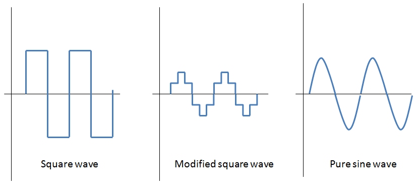
Inverters - devices that convert DC power coming from the solar modules to AC power (necessary for grid) are critical components of any PV systems. Inverters convert DC power from the batteries or solar modules into 60 or 50 Hz AC power. As with all power system components, the use of inverters results in energy losses due to interferences. Typical efficiency of an inverter well matched to the array is around 90%. Inverters are key components in both grid-connected and distributed power applications, and usually are a significant part of system cost. The AC current produced by inverters can have square, modified sine, and pure sine wave output (Figure 6.2). The pure sine is high cost and has the best power quality. The modified sine is medium cost, but has less efficiency. The square wave is low cost and lowest efficiency, which is only used by some applications. Square wave signals can be harmful to certain electronics due to high-voltage harmonic distortion. Inverters are common sources of electromagnetic noise, which can interfere with sound and video equipment. So, the inverters boxes must be grounded according to the code requirement and safety reasons [Foster et al., 2010].

Grid-tied inverters are used to tie the PV system to the utility grid. They convert DC power to AC power in synchronization with the grid. For example, if grid fails for any reason, the inverter will shut down as well. The main considerations related to PV-grid interconnection include safety, power quality, and anti-islanding. Islanding is the condition when in case of power grid going down, inverter attempts to power the grid and can result in equipment damage and safety risks to technical personnel. Grid power line with PV modules connected to it is a typical islanding situation. After the grid is down, the PV panels still continue to power the line as long as the solar radiation is present. Thus, we have an "island" of powered line within un-powered grid. Most AC grid-ties inverters have anti-islanding feature, so the inverter will reduce power to zero within 2 seconds of the grid shut-down.
Inverters are rated by the total power capacity (from hundreds to a million watts). Some inverters have a good surge capacity for starting motors, but others may have limited surge capacity. So, designers should specify both type and size of the load to be connected to the inverter [Kalogirou, 2009].
DC-DC converters or transformers are used to step up (boost) or step down (buck) voltage of DC current. Therefore, the voltage of the solar array can be chosen independently of the voltage of the load. This kind of convenience comes with a cost - DC-DC converter always have losses, although the good models have efficiency as high as 95%, with some waste heat generated [Mertens and Hanser, 2013]. Ideally (if there were no losses):
\[{P_1} = {V_1} \times {I_1} = {V_2} \times {I_2} = {P_2}\]
Where V1 and I1 are voltage and current at the input (from solar module) and V2 and I2 are voltage and current at the output, respectively.
Batteries are used in many types of PV systems to supply power at low sun conditions (night or low irradiance). Additionally, batteries are required in solar systems because of the fluctuating nature of the PV output. The battery size/capacity is selected according to the load. They are usually connected in parallel to match higher capacity. There are several types of batteries commercially available for solar applications, including lead-acid, nickel-cadmium, nickel hydride, and lithium-ion. The main requirement for the batteries that are used as energy storage for solar systems is that they must be able to go through deep charging and discharging cycles without too much degradation. Batteries are classified by the nominal capacity (qmax), which is the maximum number of ampere-hours that can be extracted from the battery under certain standard conditions.
The efficiency of a battery can be defined as the ratio of the charge extracted during discharge to the amount of charge needed to restore that state of charge. The efficiency depends on State of Charge (SOC), which is the ratio between the present capacity of the battery and the nominal capacity (SOC = q/qmax). For example, SOC=1 when the battery is fully charged, and SOC=0 when the battery is fully discharged. The battery lifetime is often presented as the number of charge-discharge cycles the battery can sustain before losing 20% of its nominal capacity [Kalogirou, 2009].
Batteries used in power generating solar systems are actually different from car batteries. The car batteries are not designed to withstand the deep charge-discharge cycles and therefore should not be used with solar power generation. Batteries are usually installed in well-ventilated locations - (e.g., utility rooms) to minimize hazards from spills and made them available for easy maintenance or replacement. More details of energy storage technology will be covered in Lesson 9.
Grounding and bonding of related DC and AC circuits is important to maintain system integrity. According to the U.S. electric code, the systems operating under 50 V are not required to be grounded, although chassis grounding is required for all hardware.
6.2. Connections in large PV systems
6.2. Connections in large PV systems
Power output from the solar arrays would be dependent on the arrangement and connection of the modules within the plant and can be varied based on local preference. To know how we can manipulate power output, we need to understand the principles of interconnections of PV cells in the modules and connections of those modules to the direct current equipment. From the following reading, you will learn about different types of connections and how they determine the module response to disturbances such as shading or formation of hot spots. Additionally, we will see how the module performance may be affected by different environmental parameters, such as irradiance, temperature, and type of solar cell material. Finally, this reading will describe how the cable connections are made between the solar modules and a generator.
Reading Assignment
Book Chapter: Mertens, K. and Hanser, K.F., Photovoltaics: Fundamentals, Technology, and Practice [2], John Wiley & Sons, 2013. Chapter 6: Solar Modules and Solar Generators, pp. 133-159. (Also see E-Reserves via the Library Resources tab.)
Note: The quiz at the end of this lesson will include a few questions on this reading. Please refer to the Summary and Activity page for more details.
6.3. Architecture of the large-scale PV systems
6.3. Architecture of the large-scale PV systems
Development of large solar PV plants has been underway in a number of countries, especially where the government-backed incentives and legislation were in place to support renewables. Since 2000, installation of MW-scale PV systems has been initiated in Germany, Spain, Italy, Greece, and further taken into even larger scale in U.S., China, India, and Brazil. The trend really picked up after 2007, when the number of the more than 1 MW systems grew from 20 to over 100 within a few years. Industry experts predict that the trend will hold and perhaps even accelerate into the future as the demand for renewable energy resources escalates. The average and maximum size of the utility solar plants (typically 5 MW to 500 MW) increases as well. The Topaz Solar Farm, located in San Luis Obispo County, California, is one of the largest solar photovoltaic power plant in the U.S. (Figure 6.3). This facility has the capacity to generate 550 megawatts (MW) of solar electricity using 5 million panels.

Credit: Pacific Southwest Region via Wikimedia [3]
_(2).jpg)
The list of the world's largest PV plants [4] is updated from year to year, and you can see that Topaz benchmark has been already beaten repeatedly now, and the top facilities currently exceed GW limit. One of the attractive factors of the utility PV plants is that those facilities can be built relatively quickly (within 6-12 months) due to modular structure, unlike major hydroelectric, geothermal, or fossil fuel facilities, which would be typically developed over 3-5 year span. This presents a great opportunity for emerging economies to effectively meet their growing energy demands, especially since many of those countries possess an excellent solar resource.
Initially, the PV plant design is developed at the stage of feasibility assessment, which includes estimation of solar resource and expected yield. Then, the plant design is further improved, taking into consideration other local limitations and constraints. The feasibility stage also includes site measurements, topography mapping, environmental setting assessment, and social impacts. Key design features include such technical information as PV module type, tilting angle, mounting and tracking systems, module arrangement, and balance of system (BOS) components - inverters, connections, switches, and storage solutions. Further optimization of plant design would deal with such issues as shading, performance degradation, and economic trade-offs between increased complexity and energy yield.
The design of a utility scale PV plant is a complex endeavor. With many available choices of components and options for optimizing performance, it is important to strike a balance between cost savings and quality. Engineering decisions require significant technical expertise and should be "informed" decisions based on both optimization models and practical experience.
The following reading will introduce the main principles of the design of very large PV systems.
Reading Assignment
Here you will have a chance to study different aspects that need to be considered during the PV plant design and construction. Advances in system architecture, civil works, operational regimes allow significant cost reductions and better marketability of the solar energy in those regions.
Komoto, K., Ito, M., van der Vleuten, P., Faiman, D., and Kurokawa, K., Energy from the Desert, Chapter 7. MW-Scale PV System Installation Technologies, pp. 86-98. (see Canvas - Lesson 6 Reading Materials)
Abbreviations in the reading:
- VLS-PV - very large scale photovoltaic
- PCU - power conditioning unit
- MVA - megavolt ampere
- DC - direct current
- AC - alternate current
- IGBT - insulated gate bipolar transistor
- EPC - engineering, procurement, construction
Following this reading, please take the reading quiz in Canvas (see Module 6).
6.4. Inverters: principle of operation and parameters
6.4. Inverters: principle of operation and parameters
Now, let us zoom in and take a closer look at the one of the key components of power conditioning chain - inverter. Almost any solar systems of any scale include an inverter of some type to allow the power to be used on site for AC-powered appliances or on the grid. Different types of inverters are shown in Figure 11.1 as examples. The available inverter models are now very efficient (over 95% power conversion efficiency), reliable, and economical. On the utility scale, the main challenges are related to system configuration in order to achieve safe operation and to reduce conversion losses to a minimum.

The three most common types of inverters made for powering AC loads include: (1) pure sine wave inverter (for general applications), (2) modified square wave inverter (for resistive, capacitive, and inductive loads), and (3) square wave inverter (for some resistive loads) (MPP Solar, 2015). Those wave types were briefly introduced in Lesson 6 (Figure 11.2). Here, we will take a closer look at the physical principles used by inverters to produce those signals.
The process of conversion of the DC current into AC current is based on the phenomenon of electromagnetic induction. Electromagnetic induction is the generation of electric potential difference in a conductor when it is exposed to a varying magnetic field. For example, if you place a coil (spool of wire) near a rotating magnet, electric current will be induced in the coil (Figure 11.3).

Next, if we consider a system with two coils (Figure 11.4) and pass DC current through one of them (primary coil), that coil with DC current can act analogously to the magnet (since electric current produces a magnetic field). If the direction of the current is reversed frequently (e.g., via a switch device), the alternating magnetic field will induce AC current in the secondary coil.

The simple two-cycle scheme shown in Figure 11.4 produces a square wave AC signal. This is the simplest case, and if the inverter performs only this step, it is a square-wave inverter. This type of output is not very efficient and can be even detrimental to some loads. So, the square wave can be modified further using more sophisticated inverters to produce a modified square wave or sine wave (Dunlop, 2010).
To produce a modified square wave output, such as the one shown in the center of Figure 11.2, low frequency waveform control can be used in the inverter. This feature allows adjusting the duration of the alternating square pulses. Also, transformers are used here to vary the output voltage. Combination of pulses of different length and voltage results in a multi-stepped modified square wave, which closely matches the sine wave shape. The low frequency inverters typically operate at ~60 Hz frequency.
To produce a sine wave output, high-frequency inverters are used. These inverters use the pulse-width modification method: switching currents at high frequency, and for variable periods of time. For example, very narrow (short) pulses simulate a low voltage situation, and wide (long pulses) simulate high voltage. Also, this method allows spacing the pulses to be varied: spacing narrow pulses farther apart models low voltage (Figure 11.5).
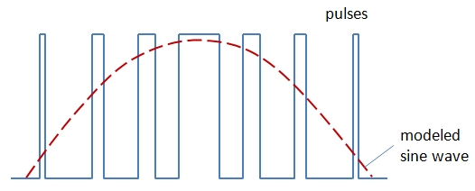
In the image above, the blue line shows the square wave varied by the length of the pulse and timing between pulses; the red curve shows how those alternating signals are modeled by a sine wave. Using very high frequency helps create very gradual changes in pulse width and thus models a true sine signal. The pulse-width modulation method and novel digital controllers have resulted in very efficient inverters (Dunlop, 2010).
6.5. Efficiency of Inverters
6.5. Efficiency of Inverters
The efficiency of an inverter indicates how much DC power is converted to AC power. Some of the power can be lost as heat, and also some stand-by power is consumed for keeping the inverter in powered mode. The general efficiency formula is:
where PAC is AC power output in watts and PDC is DC power input in watts.
High quality sine wave inverters are rated at 90-95% efficiency. Lower quality modified sine wave inverters are less efficient - 75-85%. High frequency inverters are usually more efficient than low-frequency.
Inverter efficiency depends on inverter load.

Figure 11.8. Typical generic inverter efficiency curve. Below 10-15% of power output, efficiency is quite low. At high output power, the efficiency is steadily high with some small variations.
The behavior in Figure 11.8 partially results from the fact that stand-by losses for an inverter are the same for all output power levels, so the efficiency at lower outputs is affected more.
There are three types of efficiency ranking used for inverters. You may come across those numbers as you research different models and manufacturers. Those three types are:
- Peak efficiency (shown by arrow in Figure 11.8) indicates the performance of the inverter at the optimal power output. It shows the maximum point for a particular inverter and can be used as a criterion of its quality.
- European efficiency is the weighted number taking into account how often the inverter will operate at different power outputs. It is sometimes more useful than peak efficiency, as it shows how the inverter performs at different output levels during a solar day.
- California Energy Commission (CEC) efficiency is also a weighed efficiency, similar to the European efficiency, but it uses different assumptions on weighing factors.
The main difference between the European and CEC efficiencies is that the assumptions about the importance of each power levels for a particular inverter are based on the data for Central Europe in the former case, and California in the latter. Hence, different formulae are used to calculate those values:
These methods of calculations need to be taken into account when using inverter specifications (Martin, 2011).
To learn more details about inverter efficiency, please go to the following reading.
Reading Assignment
Book chapter: Mertens, K and Hanser K.F., Photovoltaics: Fundamentals, Technology and Practice [2], Chapter 7, Section 7.2.4 Efficiency of Inverters, pp. 177-181.
Please answer the following self-check questions based on the above material.
Check Your Understanding
Question 1
What is the efficiency of an inverter that outputs 2000 W of AC power using an input of 2200 W of DC power?
Question 2
Question 3
See if you can estimate the European efficiency for an inverter that has the following efficiency curve data: at 5% power output η=85%, at 10% η=91%, at 20% - η=96%, at 30% η=97%, at 50% η=96%, and at 100% power η=95%. Input your value below, compare with the answer.
6.6. Switching devices
6.6. Switching devices
Switching function in inverters is needed to alternate the direction of the DC current in order to produce AC power. Usually, electronic semiconductor devices are used to perform switching, such as transistors and thyristors.
Thyristors are used in basic models of inverters. They have three leads and usually "switch on" in response to current applied to one of the leads. Thyristor have only two modes: ON and OFF, the same as mechanical switches. More details on thyristors can be found on this Thyristor Wikipedia Page. [6]
Transistors are similar in switching capability to thyristors, but they instead respond to voltage applied rather than current. That allows to smoothly vary the transistor's internal resistance. So in addition to ON and OFF functions, transistors also allow dimmer capability. More details on transistors can be found on this Transistor Wikipedia Page [7].
There are two main types of transistors used in solar inverters:
- Metal Oxide Semiconductor Field Effect Transistors (MOSFETs)
- Insulated Gate Bipolar Transistors (IGBTs)
The MOSFET type is suitable for very high switching speeds (up to 800 kHz), but operate at relatively low voltage. The IGBT type switch at lower speeds (below 20 kHz), but withstand higher voltage and high current (Dunlop, 2010).
Switching Control
Switching devices, such as thyristors and transistors, need to be controlled by an external signal. In the basic inverter designs, switching is controlled by the utility power line. Such switching devices are referred to as line-commutated. They are turned on and off by alternating half-cycles of the utility voltage, thus synchronizing the inverter output with grid line current. Although efficient, the line-commutated inverters have one disadvantage: they cannot operate independently of the grid.
Some inverters may contain an internal device that controls switching. Such a device is usually a microprocessor that provides precise timing. Such inverters are called self-commutated. Self-commutated inverters have additional capabilities of shaping the AC output and suppressing harmonics. And they can operate independent of utility power. There are two varieties of self-commutated inverters: voltage-source and current-source. They take the DC input as voltage source or current source, respectively, for conversion of the power to the AC output. Most of the present day inverters involved in solar plants are self-commutated (Dunlop, 2010).
6.7. DC/DC Conversion
6.7. DC/DC Conversion
A typical output voltage of PV panels can be on the order of 30 V, and it is too low for being converted to AC and fed to the grid. Therefore, DC/DC conversion is often a necessary step before the DC current from the PV system is supplied to the inverter. Most of the power conditioning units include some type of DC/DC converter. Direct current converter transforms the DC voltage V1 to DC voltage V2 via adjusting the current (I):
This is an ideal case, when input power is equal to the output power. In reality, there are always conversion losses, which lead to typical efficiencies in the range 90-95%.
DC/DC conversion allows keeping the voltage on the PV and voltage on the load separately controlled. There are two main types of DC/DC converters depending on the direction of voltage change: (1) boost converters transform smaller voltage to higher voltage and (2) buck converters transform higher voltage to lower voltage.
Please proceed to the following reading to learn more details about the operating principles of the DC/DC converters.
Reading Assignment
Book chapter: Mertens, K and Hanser K.F., Photovoltaics: Fundamentals, Technology and Practice [2], Chapter 7, Section 7.1.2 DC/DC Converter, pp. 161-168. (also aee E-Reserves via the Library Resources tab.)
MPP tracking
One of the important functions that DC/DC converting devices can perform is maximum power point (MPP) tracking. The idea behind it is to keep the solar power system operating constantly at the maximum power, i.e., at the voltage Vmp and current I mp. These parameters were discussed in Lesson 4, and Figure 4.4 illustrates the concept.
Assume that at a certain ambient irradiance, a solar cell or an array operate at the maximum power. Then, if the irradiance conditions change, the performance characteristic (I-V curve) of the cell changes (Figure 11.6). Thus, if the output voltage is kept constant, the output current drops significantly. The MMP tracker is used to adjust the voltage to the new Vmp value, thus maintaining the maximum power output.

I-V performance curves of a solar cell in varying sunlight. The upper curves demonstrate the cell performance at higher irradiance conditions. The vertical path crossing the performance curves indicates the shift of the maximum power point.
In large solar facilities, it is beneficial to have an individual MPP tracking unit to be connected to each array output, since different arrays may have different I-V characteristics (due to varying irradiance, orientation etc.). This improves the overall performance of the plant.
An algorithm for MPP tracking is discussed in Section 7.1.3 of the above-referenced reading.
Please answer the following self-check questions before proceeding to the next section.
Check your understanding
Question 4. The principle of the buck DC/DC converter is based on periodically switching on and switching off the signal and then smoothing the output. Which parameter is used to regulate the switch-on/switch-off regime?
Question 5. Can you calculate the output of the boost DC/DC converter that uses the duty factor of 0.6 to convert 10 V of DC?
6.8. PV--Grid connection
6.8. PV--Grid connection
Interconnections in solar systems and their connection to the public grid are regulated by National Electrical Code®(NEC). The NEC is a nationally recognized standard for safe electrical installation and is routinely applied all over the U.S. It is intended for use by trained personnel and is applied to integration of all wiring, overcurrent protection, disconnects, grounding, and equipment regulations. Article 690 of NEC is specifically dedicated to solar photovoltaic systems, and article 490 is applied to large utility-scale systems (over 600 V). Importantly, the NEC addresses the circuit requirements for solar systems, such as maximum current and voltage.
Maximum Voltage Rating
The first condition for determining the maximum DC voltage is that it should be lower than the voltage limits defined for any component on the DC side of the system. The maximum DC voltage output (Vmax) from a PV system can be estimated using the following formula (Dunlop, 2010):
where Voc is the open circuit voltage of a module at 25 oC, nser is the number of modules connected in series, and CT is the temperature correction factor. The CT factors account for the voltage increase with decreasing temperature and can be found in Table 690.7 in Article 690—Solar Photovoltaic (PV) Systems [9] of NEC.
For Example
What would be the total maximum output voltage of the system including 20 modules connected in series, each module having open circuit voltage of 18 V, if the minimum expected temperature at the locale is -25 oC?
Applying the formula (11.1):
Maximum Current Rating
Per NEC code Article 690.8, which deals with circuit sizing and rating, there are two different PV circuits distinguished:
(1) PV source circuits - conductors between PV modules and to the common point of connection, i.e., junction box
and
(2) PV output circuits - conductors between the junction box and the inverter or DC loads
These two types of circuits are schematically shown in Figure 11.7. The PV source circuits and PV output circuits are rated differently with respect to the maximum current.

The maximum DC current rating for PV source circuits is considered at 125% of the sum of all short-circuit currents rating of all modules. This assumption is based on the fact that under enhanced irradiance conditions, modules can occasionally generate currents higher than nominal Isc values. The maximum source current is determined for each single string.
For example:
If the module short circuit current , then
The maximum DC current rating for PV output circuit needs to take into account all parallel strings, and in this case the source maximum current needs to be multiplied by the number of strings (npar) involved in the system.
For example:
If we have three parallel strings of modules (like shown in Figure 11.7), each with source maximum current of 6 A, then
In summary, the cables within each string should be able to withstand currents of 6 A, but the cables on the inverter side should be ready for 18 A.
The estimates of the system maximum voltage and currents are key factors for choosing the inverters, determining wiring, conductor size, and required overcurrent protection.
Interconnection types
By the type of interconnections, there are several inverter types employed at different PV systems. They include stand-alone, interactive, and bimodal inverters.
The stand-alone mode does not involve grid connection, but rather uses the battery storage to collect the power from PV and convert it to AC for specific applications (Figure 11.8a). If the battery storage is depleted, the system becomes stressed.
The interactive mode does not use any energy storage, and the inverter serves as the interface between the PV and the utility grid (Figure 11.8b). In this case, power can flow in both directions. If the on-site power demand is higher than the amount supplied from the PV, the system can draw power from the grid. If the produced power is greater than the on-site power demand, the excess power is fed to the grid.
Finally, the bimodal connection (Figure 11.8c) combines both stand-alone and interactive options. Here, the energy storage provides backup for critical loads, while the excess power is fed to the grid, like in the interactive mode. If for any reason the grid loses power, this bimodal system uses a separate dedicated distribution panel to support the critical loads (such as computers, lighting, water pumping, etc.) (Dunlop, 2010).

Please refer to the following reading to gain more insight in inverter operation in grid-connected systems.
Reading Assignment
Book chapter: Mertens, K and Hanser K.F., Photovoltaics: Fundamentals, Technology and Practice [2], Chapter 7, Section 7.2 Grid Connected Systems, pp. 168-177. (also see E-Reserves via the Library Resources tab.)
Grid-connection challenges
The following are some known concerns arising from interconnection of different scale PV systems to the utility grid.
- Islanding is the condition when the solar power facility keeps supplying power to the grid during grid outage. This is a serious safety hazard, since utility workers who repair the grid may be exposed to unexpected voltage present in the utility line. To prevent damage to personnel and equipment, all grid-bound inverters must be able to detect outages and block power transfer. Inverters with such capability are referred to as anti-islanding inverters. Bimodal inverters may remain in stand-alone mode of operation while being disconnected from the utility grid line.
-
Power quality is reflected in the several electrical performance parameters, such as voltage, frequency, harmonic distortion, noise, etc. Many loads and equipment connected to the grid are designed to operate at certain prescribed conditions and may not be able to withstand voltage fluctuations and other disturbances. Low-quality inverters can cause poor power quality, which can cause damage to the sensitive equipment, or create hotspots in transformers.
-
Phase disbalance can occur if single-phase inverters are connected to three-phase power systems. Solution to the mismatch may be connection of three small inverters, each to a different phase, or employing a single three-phase inverter.
Please answer the following self-check questions before proceeding to the next section.
Check your understanding
Question 6. Will the PV cell voltage be higher or lower if the outdoor temperature drops to -10 oC? Find the temperature correction factor for this case.
Question 7. If a PV cell outputs 20 V at 25oC, what voltage can we expect from it at -10oC?
Question 8. Which of the following is usually true with grid-connected solar plants?.
Additional Reading on Inverters
Dunlop, J.P., Photovoltaic Systems, 2nd Ed., Chapter 8: Inverters. American Technical Publishers, 2010.
King, D.L., Gonzalez, S., Galbraith, G.M., and Boyson, W.E., Performance Model for Grid-Connected Photovoltaic Inverters [10], Sandia Report SAND2007-5036, 2007.
Summary and Final Tasks
Summary and Final Tasks
This lesson addresses multiple issues related to the scale up and deployment of photovoltaic technology. PV arrays generate DC power, sometimes a lot of it. It takes a lot of hardware and engineering effort to use that power safely and efficiently. Here, we looked into the principles of connection of various components within PV plants, overviewed the key pieces of equipment necessary for plant operation, and became familiar with some engineering practices used in construction and servicing of very large scale PV systems. We also discussed some technical aspects related to transformation of the energy supplied by PV into the usable grid power. Although the technologies involved in power conversion and conditioning are not directly solar, but rather supporting systems, it is important to understand their types, role, and specifications.
Please complete the following activities to complete this lesson.
| Type | Description / Instructions | Deadline |
|---|---|---|
| Readings | Complete all necessary reading assigned in this lesson. | |
|
Reading Quiz |
This assignment presents you with a set of questions based on the readings assigned in this lesson. |
Wednesday night |
| Yellowdig Discussion |
Grid Safety Consider this scenario: A customer who has grid-connected PV modules on their property finds themselves in the natural disaster zone. Power is down! Can the customer use the PV generator to power their property? To answer this question competently, you may need to explore safety requirements for inverters for grid-bound PV systems. What is UL 1741 SA and how is it related to utility grid regulations? (Resource: https://www.energy.gov/energysaver/grid-connected-renewable-energy-systems [11])
|
The point-earning period for this week runs from Saturday to next Friday. |
References for Lesson 11
Dunlop, J.P., Photovoltaic Systems, 2nd Ed., American Technical Publishers, 2010.
Martin, J II, Types of Solar Inverter Efficiency, Solar Choice, 2011. Accessed via URL: http://www.solarchoice.net.au/blog/types-of-solar-inverter-efficiency/ [12]
Mertens, K and Hanser, K.F., Photovoltaics: Fundamentals, Technology and Practice [2], John Wiley & Sons, 2013.
MPP Solar, Schematic and operation of an inverter, 2014-2015. Accessed via URL: http://www.mpptsolar.com/en/how-does-an-inverter-work.html [13]
Foster, R., Ghassemi, M., and Cota, A., Solar Energy. Renewable Energy and the Environment, CRC Press 2010.
Kalogirou, S.A., Solar Energy Engineering. Processes and Systems, Elsevier 2009.