Lesson 10: Global Navigation Satellite Systems and the Future
The links below provide an outline of the material for this lesson. Be sure to carefully read through the entire lesson before returning to Canvas to submit your assignments.
Lesson 10 Overview
Overview
The GPS system is one component of the worldwide effort now known as the Global Navigation Satellite System, GNSS. Another component of GNSS is the GLONASS system of the Russian Federation, a third is the GALILEO system administered by the EU and a fourth is the Chinese Beidou system. The concept is the use of these networks of satellites and others together. Further, they will be augmented by both ground-based augmentation systems, GBAS, and space-based augmentation systems, SBAS, to provide positioning, navigation, and timing solutions to users around the world. One goal of this cooperation is interoperability. Interoperability is the idea that properly equipped receivers will be able to obtain useful signals from all available satellites in all the constellations and have their solutions improved rather than impeded by the various configurations of the different satellite broadcasts.
Objectives
At the successful completion of this lesson, students should be able to:
- recognize the benefits of L1C;
- define BPSK modulation scheme;
- define BOC modulation scheme;
- explain the difference between BPSK and BOC modulation schemes;
- define the GLONASS FDMA approach and GLONASS Signals;
- define the GPS CDMA approach;
- differentiate between the GLONASS FDMA approach and the GPS CDMA;
- recognize the use of leap seconds in GLONASS and GLONASS Time;
- define GALILEO;
- describe the significance of GIOVE A and GIOVE B;
- define GALILEO signals;
- define Beidou/Compass;
- identify the Quasi-Zenith Satellite System and the Indian Regional Navigation Satellite System (IRNSS) aka NavIC; and
- recognize the potential of GPS interoperability with GLONASS and GALILEO systems.
Questions?
If you have any questions now or at any point during this week, please feel free to post them to the Lesson 10 Discussion Forum. (To access the forum, return to Canvas and navigate to the Lesson 10 Discussion Forum in the Lesson 10 module.) While you are there, feel free to post your own responses if you, too, are able to help out a classmate.
Checklist
Lesson 10 is one week in length. (See the Calendar in Canvas for specific due dates.) To finish this lesson, you must complete the activities listed below. You may find it useful to print this page out first so that you can follow along with the directions.
| Step | Activity | Access/Directions |
|---|---|---|
| 1 | Read the lesson Overview and Checklist. | You are in the Lesson 10 online content now. The Overview page is previous to this page, and you are on the Checklist page right now. |
| 2 | Read "Global Positioning System and Global Navigation Satellite System" pages 284 to 302 in Chapter 8 in GPS for Land Surveyors. | Text |
| 3 | Read the lecture material for this lesson. | You are currently on the Checklist page. Click on the links at the bottom of the page to continue to the next page, to return to the previous page, or to go to the top of the lesson. You can also navigate the lecture material via the links in the Lessons menu. |
| 4 | Participate in the Discussion. | To participate in the discussion, please go to the Lesson 10 Discussion Forum in Canvas (That forum can be accessed at any time by going to the GEOG 862 course in Canvas and then looking inside the Lesson 10 module.) |
| 5 | Take the Final Quiz. | The Final Quiz is located in the Lesson 10 module in Canvas. |
| 6 | Read lesson Summary. | You are in the Lesson 10 online content now. Click on the "Next Page" link to access the Summary. |
GNSS


Click here to see a text description.
GPS
- 6 Orbital Planes
- 24 satellites + spare
- 55 degree inclination angle
- altitude 20,200 km
Galileo
- 3 Orbital Planes
- 27 Satellites + 3 Spares
- 56 degree inclination angle
- altitude 23,616 km
GLONASS
- 6 Orbital Planes
- 35 satellites: 5 GEO, 27 MEO, 3 IGSO
- 64.8 degree inclination angle
- altitude 19,100 km
Beidou
- 3 Orbital Planes
- 21 satellites + 3 spares
- 55 degree inclination angle
- altitude 38,300 km 21,200km
It may be a bit unexpected, but many of the plans that will change GPS as a practical utility will be implemented entirely outside of the GPS system itself. The GPS system is one component of the worldwide effort known as the Global Navigation Satellite System (GNSS). Another component of GNSS is the GLONASS system of the Russian Federation, a third is the Galileo system administered by the EU and a fourth is the Chinese Beidou system. It is likely that more constellations will be included in GNSS, such as the Japanese Quasi-Zenith Satellite System (QZSS), the Indian Regional Navigation Satellite System (IRNSS) aka NavIC. They will be augmented by both ground-based augmentation systems (GBAS) and space-based augmentation systems (SBAS) deployed by the United States, Europe, Japan, China, and Australia. One immediate effect of GNSS is the substantial growth of the available constellation of satellites; the more signals that are available for positioning and navigation, the better. The concept is that these networks of satellites and others will begin to work together to provide positioning, navigation, and timing solutions to users around the world.
As you see right here in this illustration, there are some obvious differences between the systems. GPS, six orbital planes; Galileo, three; GLONASS, three and Beidou, three. The number of satellites really is somewhat consistent in each case. The inclination angle is 55 degrees for GPS; 56 degrees for Galileo, 64.8 degrees for GLONASS and 55 degrees for Beidou. The altitudes are similar. GPS in the middle and Galileo somewhat higher and GLONASS somewhat lower. Beidou has one plane higher than the rest at 38,300 km for their Inclined Geosynchronous Orbit. This is so one satellite will be over Chinese territory at all times. This is, in part, to overcome troubles acquiring a signal in obstructed environments.

The International GNSS Service (IGS) is a service of the International Association of Geodesy and the Federation of Astronomical and Geophysical Data Analysis Services that was originally established in 1993. Like NGS, IGS also provides CORS data. However, it has a global scope. The information on the individual stations can be accessed, including the ITRF Cartesian coordinates and velocities for the IGS sites, but not all the sites are available from IGS servers. One example of the scope of this increased horizon in global positioning is illustrated by the name change of the International GPS Service to the International GNSS service, IGS.

GLONASS

Click here to see a text description.
GLONASS
- 3 Orbital planes
- 21 Satellites + 3 Spares
- 64.8 degree inclination angle
- Altitude 19,100 km
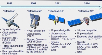
Russia’s (Globalnaya Navigationnaya Sputnikovaya Sistema, Global Orbiting Navigation Satellite System), known as GLONASS, did not reach full operational status before the collapse of the Soviet Union. Its first of the Uragan satellites reached orbit in October 1982, a bit more than 4 years after the GPS constellation was begun. There were 87 Uragan satellites launched, and a nearly full constellation of 24 made up of 21 satellites in 3 orbital planes, with 3 on-orbit spares was achieved in 1996. However, only about 7 healthy satellites remained on orbit, about 1000 km lower than the orbit of GPS satellites in 2001. And the remaining 7 were only expected to have a design life of 3 years. The situation was not helped by the independence of Kazakhstan, subsequent difficulties over the Baikonur Cosmodrome launch facility, and lack of funds. The system was in poor health when a decision was taken in August 2001 outlining a program to rebuild and modernize GLONASS. Improvements followed.

Today, Russia’s GLONASS is operational and has worldwide coverage. A complete GLONASS constellation of improved satellites is in place at the altitude of 19,100 km inclined 64.8 degrees toward the Equator as shown in the illustration. The original GLONASS satellite was the Uragan. It was first launched in 1982 and had an intended life-span of 4 years. Compared with the Uragan satellites, the Uragan-M have several new attributes. These satellites have improved antennas, an increased lifetime of 7 years, improved solar array orientation, better clock stability and better maneuverability. They are 3-axis stabilized, have on-board cesium clocks. Launched between 2001 and 2014, they were augmented with an L2 frequency for civilian users in 2004. These satellites comprise most of the current GLONASS constellation.

The GLONASS K satellite is lighter than the Uragan-M. It has an unpressurized bus, a 12 year service life, and costs less to produce. These satellites also carry the international search and rescue instrument COSPAS-SARSAT. As the Uragan-M satellites age, they will be replaced by the smaller GLONASS-K satellites.

GLONASS Uragan K2 satellite
Source: https://space.skyrocket.de/doc_sdat/uragan-k2.htm
They will be followed by further improved versions known as GLONASS-K2. It will be launched around 2022. A passive hydrogen maser (PHM) will be validated onboard. A later improvement is known as GLONASS-KM. It is in research phase, will be launched around 2025. As shown in the illustration, the K version of the GLONASS has a transmitter for a third L-band civilian signal. As you know, we've talked about L5, the new carrier. They will soon be available on the GPS constellation, and the GLONASS constellation is following somewhat the same pattern. The plan is to have a carrier that will be available on a third frequency for the civilian users.

GLONASS K (left), GLONASS M (Right
Source: http://www.russianspaceweb.com/glonass_deployment.html
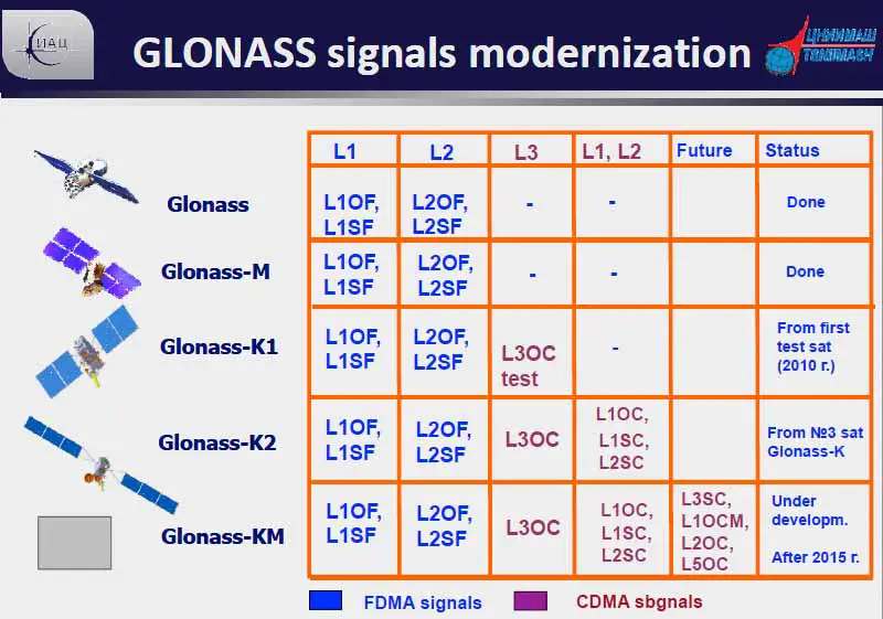
GLONASS Satellites and Signals

Regarding the signals broadcast by the GLONASS satellites, the original objective was similar to the plan embraced by GPS, a system that would provide 100 meters accuracy with a deliberately degraded standard C/A signal and 10- to 20-meter accuracy with its P signals available exclusively to the military. However, that changed at the end of 2004, when the Federal Space Agency (FKA) announced a plan to provide access to the high-precision navigation data to all users whose foundation is a right-hand circular polarized code-based solution.

A receiver collecting signals from GPS, or from most other GNSS constellations, for that matter, collects a unique segment of the PRN code from each satellite. For example, a particular segment of the 37-week long P(Y) code is assigned to each GPS satellite; i.e., SV14 is so named because it broadcasts the fourteenth week of the P(Y) code. Also, each GPS satellite broadcasts its own completely unique segment of the C/A code.

Simultaneous
Souce: http://www.pocketgpsworld.com/howgpsworks.php
Even though the segments of the P(Y) code and the C/A code coming into a receiver on L1 are unique to their satellite or origin, they all arrive at the same frequency, 1575.42 MHz. The same is true of the P(Y) code that arrives on L2. They all arrive at the same frequency, 1227.60 MHz.

This approach is known as CDMA (Code Division Multiple Access). CDMA technology was originally developed by the military during World War II. Researchers were looking for ways of communicating that would be secure in the presence of jamming. CDMA does not use frequency channels or time slots. The technique is called multiple access because it serves many simultaneous users, and CDMA does this over the same frequency. As in GPS, CDMA usually involves a narrow band message multiplied by a wider bandwidth PRN (pseudorandom noise) signal. The increased bandwidth is wider than necessary to broadcast the data information and is called a spread spectrum signal. As you have read, these PRN codes are attached to the GPS carrier by changes in phase. Then all the users can receive the same frequency bands. To make this work, it is important that each of the PRN codes, C/A, P(Y), and all the others, have high autocorrelation and low cross-correlation properties. High autocorrelation promotes efficient de-spreading and recovery of the unique code coming from a particular satellite which includes matching it with the PRN code available for that satellite inside the receiver. Low cross-correlation means that the autocorrelation process for a particular satellite’s signal will not be interfered with by any of the other satellite’s signals that are coming in from the rest of the constellation at the same time. With CDMA, each code that comes from a satellite is broadcast on one of the three unique carrier frequencies, L1, L2, L5. There is a difference between the original scheme in the GLONASS system and the GPS. There's a difference between CDMA and FDMA.

GLONASS used a different strategy from its beginnings. As shown in illustration, the satellites transmit L-band signals, and, unlike GPS, each code a GLONASS receiver collects from any one of the GLONASS satellites is exactly the same. Also, unlike GPS, each GLONASS satellite broadcasts its codes at its own unique assigned frequency. This is known as FDMA (Frequency Division Multiple Access). This ensures signal separation known as an improved Spectral Separation Coefficient (SSC). However, the system does require more complex hardware and software development. Unlike GPS, each code a GLONASS receiver collects from any one of the GLONASS satellites is exactly the same. However, each is at a different frequency. All GPS satellites use the same frequencies but different segments of code. All GLONASS satellites use the same codes but different frequencies.

The three GLONASS L bands have a range of frequencies to assign to satellites. GLONASS uses carriers in three areas. The first is L1 (~1602 MHz), in which the separation between individual carriers is 0.5625 MHz; the range is between ~1598.0625 to ~1607.0625 MHz. The second is L2 (~1246 MHz), in which the separation between individual carriers is 0.4375 MHz; the range is between ~1242.9375 to ~1249.9375 MHz. The third is L3. This third civil signal on L3 is available on the K satellites and within a new frequency band (~1201 MHz) that includes 1201.743 to 1208.511 MHz and will overlap Galileo’s E5B signal. On L3, there will be a separation between individual carriers of 0.4375 kHz. However, within those ranges, there can be up to 25 channels of L-band signals; currently there are 16 channels on each to accommodate the available satellites.
Please note in the illustration, the -7 on the left and the +9 on the right for a total range from the center of 16. As mentioned, each channel is separated from the others by a ?F which is 0.5625 MHz on L1 and 0.4375MHz on L2. There could be up to 25 channels of L-band signals. This number is needed so that each satellite in the GLONASS constellation can have its own small frequency segment. Those are the little bumps that you see in the illustration. In other words, each GLONASS satellite broadcasts the same code, but each satellite gets its own frequencies.
The standard code chip lengths on the GLONASS L1 are 0.511MHz – 3135.03 L1 cycles/chip standard and 5.11 MHz precise – 313.503 L1 cycles/chip. On L2, they are 0.511MHz – 2438.36 L2 cycles/chip standard and 5.11 MHz precise – 243.836 L2 cycles/chip. Obviously, the faster one is the precise code. On L2, they are 0.511 MHz standard, and 511 MHz precise – the faster, of course, being the precise code. And there is, of course, this delineation between the precise and the standard service in GLONASS just as there is in GPS.


Signals transmitted by the different generations of GLONASS satellites.
OF 5 open-access FDMA
SF 5 special (military) FDMA
OC 5 open-access CDMA
OCM 5 open-access CDMA modernized.
The head of the Russian GNSS Mission Control Center announced a plan in his February 20, 2008 presentation to the Munich Satellite Navigation Conference in Germany that CDMA signals would be tested in the GLONASS system beginning with the GLONASS-K generation of satellites. In fact, since its launch in February 2011, a Uragan K or GLONASS-K satellite has been broadcasting a CDMA signal on L3 which is centered on 1202.025 MHz along with an FDMA signal. There are more broadcasts of CDMA from GLONASS satellites coming, as you can see from the chart. As things develop further, the satellites in the GLONASS constellation will include GLONASS-M, GLONASS-K1, GLONASS-K2, and GLONASS-KM. The GLONASS-K2 satellites have a 10-year design life and carry a CDMA civil signal at L3 band in the 1205 MHz frequency. A modernized GLONASS-K satellite (GLONASS-KM) could transmit the legacy FDMA signals on L1 and L2 and CDMA signals on L1, L2, and L3. It could also transmit CDMA signals on the GPS L5 frequency at 1176.45 MHz. GNSS integrity information could also be broadcast in the third civil signal and global differential ephemeris and time corrections.

GLONASS Constellation
Source: GPS for Land Surveyor
Also, an alternative to the present three-plane, equally spaced satellite constellation, which would also require the legacy FDMA signals be switched off is also being studied. In other words, there may be some changes to the FDMA approach in the future. Recently, Russia agreed to alter the architecture a bit. In order to use only half as many bands, GLONASS will now assign the same frequency to satellites that are in the same orbital plane but are always on opposite sides of the earth. This will not only reduce the amount of the radio spectrum used by GLONASS; it may actually improve its broadcast ephemeris information. Utilizing so many frequencies makes it difficult to accommodate the wide variety of propagation rates and keep the ephemeris information sent to the receivers within good limits. There are a number of receiver manufacturers that have GPS/GLONASS receivers available, but the differences between FDMA and CDMA signals increase the technical difficulty and costs of such equipment. In the last few months of 2006, it was mentioned that GLONASS probably will be able to implement CDMA signals on the third frequency and at L1. This could make it easier for GPS and Galileo to be interoperable with GLONASS and will probably improve GLONASS’s commercial viability.

Both satellites are transmitting on the same frequency
Source: https://novatel.com/an-introduction-to-gnss/chapter-3-satellite-systems/...
Changes to FDMA. There may be some changes to the FDMA approach in the future. Recently Russia agreed to alter the architecture a bit. In order to use only half as many bands GLONASS will now assign the same frequency to satellites that are in the same orbital plane but are always on opposite sides of the Earth. This will not only reduce the amount of the radio spectrum used by GLONASS it may actually improve its broadcast ephemeris information. Utilizing so many frequencies makes it difficult to accommodate the wide variety of propagation rates and keep the ephemeris information sent to the receivers within good limits. There are a number of receiver manufacturers that have GPS/GLONASS receivers available but the differences between FDMA and CDMA signals increases the technical difficulty and costs of such equipment. In the last few months of 2006 it was mentioned that GLONASS probably will be able to implement CDMA signals on the third frequency and at L1. This could make it easier for GPS and GALILEO to be interoperable with GLONASS.
GLONASS Time and Ephemeris

GLONASS Time
There are many efforts underway to improve the GLONASS accuracy. The stability of the satellites’ onboard clocks has improved from 5 x 10–13 to 1 x 10–13 over 24 hours with precision thermal stabilization. The GLONASS Navigation Message will include the difference between GPS time and GLONASS time, which is significant. There are no leap seconds introduced to GPS Time. The same may be said of Galileo and BeiDou. However, things are different in GLONASS. Leap seconds are incorporated into the time standard of the system. Therefore, there is no integer-second difference between GLONASS Time and UTC, as there is with GPS. The effect is that there's a difference between the time standards in terms of integer seconds, whole seconds, and that difference changes from time to time.

Still, that is not the whole story. The version of UTC used by GLONASS is the Coordinated Universal Time of Russia. The epoch and rate of Russian time, relative to UTC (BIH), is monitored and corrected periodically by the Main Metrological Center of Russian Time and Frequency Service (VNIIFTRI) at Mendeleevo (Moscow Region).

GNSS Time References
Source: http://www.chronos.co.uk/files/pdfs/itsf/2015/day3/1105_ITSF_2015_GNSS_T...
They establish the regional version of UTC known as UTC(SU). There is a constant offset of 3 hours between GLONASS Time and UTC (SU). GLONASS Central Synchronizer,CS, time is the foundation of GLONASS time, GLONASST. The GLONASS-M satellites are equipped with cesium clocks, which are kept within 8 nanoseconds of GLONASST.
GLONASS Ephemeris
The phase center of the satellite’s transmitting antennas is provided in the PZ-90.11 Earth-Centered Earth-Fixed reference frame in the same right-handed three-dimensional Cartesian coordinate system described in earlier lessons. All GLONASS satellites broadcast in accordance with PZ-90.11 (close to ITRF2000). They started to do so at 3:00 pm on December 31, 2013.
GLONASS Constellation
The GLONASS constellation currently has 30 operational satellites on orbit.
Galileo

The European Union’s civilian-controlled Galileo system is approaching operational status. The satellites are on orbit at a nominal height of about 23,222 km above the Earth. There are currently 22 usable satellites on orbit. The full constellation will include 30 satellites in 3 planes, 10 in each plane, higher than the GPS constellation. There are four carriers: E5a (1176.45 MHz), E5b (1191.795 MHz), E6 (1278.75 MHz) and E2-L1-E1 (1575.42 MHz). Galileo is intended to have worldwide coverage. It uses CDMA as its access scheme. And it will be interoperable with GPS and GLONASS.

GIOVE-A
Just over a dozen years after the idea was first proposed, the work on Galileo culminated in the launch of GIOVE-A (Galileo In Orbit Validation Experiment-A) on December 28, 2005. The name GIOVE, Italian for Jupiter, was a tribute to Galileo Galilei, discoverer of Jupiter’s moons. The first follow-on satellite, GIOVE-B was launched in 2008. It was more like the satellites that will eventually comprise the Galileo constellation than was GIOVE-A. One of the motivations for launching GIOVE-A and GIOVE-B was to allow European government authorities to register their Galileo frequencies with international regulators at the International Telecommunications Union. Registration is necessary to prevent the frequency registration from expiring. They did their job and bought time for Europe to build additional satellites without facing a confiscation of its frequency reservations. The experimental satellites also facilitated investigation of the transmitted Galileo signals and provided measurements of the radiation environment. GIOVE-B also demonstrated the utilization of a hydrogen maser frequency standard. Both satellites did their job and were retired in 2012.

Soyuz
Source: https://www.esa.int/Applications/Navigation/Europe_s_navigation_pioneer_...
Two In-Orbit Validation (IOV) satellites were launched from French Guiana in 2011 and two more in 2012. They are Galileo-IOV PFM (GSAT0101, Thijs), Galileo-IOV FM2 (GSAT0102, Natalia), Galileo-IOV FM3 (GSAT0103, David) and Galileo-IOV FM4 (GSAT0104, Sif). The first ground location using these four satellites was accomplished at the European Space Agency’s, ESA, Navigation Laboratory in Noordwijk, the Netherlands in 2013. The fifth and sixth Galileo satellites were also launched from French Guiana in 2014. The satellites initially entered elliptical orbits instead of the required circular orbits. These IOV Galileo satellites have been launched aboard Russian Soyuz rockets, and it is possible that the orbit difficulty was caused by a malfunction of the third stage of the Soyuz launch vehicle.

Click here to see a text description.
Galileo
- 3 Orbital planes
- 27 Satellites + 3 Spares
- 56 degree inclination angle
- Altitude 23,222km
In 2014 Galileo began to build Full Operational Capability (FOC). The most recent FOC satellites were the 4 launched together 7/25/2018
Galileo Signals and Services

Click here to see a text description.
| Category | Type | Description |
| Navigation | Open Access | This will be 'free to air' and for use by the mass market; simple timing and positioning down to 1m |
| Navigation | Commercial | Encrypted; High accuracy at the cm scale; guaranteed service for which service providers will charge fees |
| Navigation | Safety of Life | Open service; for applications where guaranteed accuracy is essential; integrity messages warn of errors |
| Navigation | Public Regulated | Encrypted; continuous availability even in time of crisis; government agencies will be main users |
| SAR | Search and Rescue | The system will pick up distress beacon locations; feasible to send feedback, confirming help is on its way |
There are four Galileo signals. E5a, E5b, E6 and E2-L1-E1. E5a and E2-L1-E1 overlap the existing L1 and L5 GPS signals. The minimum power received from the Galileo signals is -152dBW more than double the power of the C/A code from GPS. There is a pilot, data-less as well as a data component in all the Galileo signals. They are broadcast in quadrature. The pilot signal enhances correlation and allows longer integration, as it does on L2C and L5 in GPS. The frequency standards in the Galileo satellites are rubidium and passive hydrogen masers.
Galileo has defined five levels of service that will be provided by the system. They include the Open Service (OS), which uses the basic signals and is quite similar to GPS and GLONASS. The OS is free and available for timing and positioning applications. The Safety of Life Service (SOL) is along the same line but provides increased guarantees including integrity monitoring, meaning that users are warned if there are signal problems. SOL will be a global service and will include both a critical level service and a less accurate non-critical level. Both SOL and OS are on the E5a, E5b and E2-L1-E1 carriers. Their availability on separate frequencies presents the ability to ameliorate the ionospheric bias.
The Public Regulated Service (PRS) is encrypted and is meant to assist public security and civil authorities. The PRS is under government control and provides significant jamming protection. PRS will be provided on E6 and E2-L1-E1. Likely applications will include emergency services, law enforcement, intelligence services, and customs.
The Search and Rescue Service (SAR) is intended to enhance space-based services and improve response time to distress beacons and alert messages. Galileo is another constellation in the COSPAS-SARSAT effort, already mentioned in the discussions of GPS and GLONASS. Transponders on the satellites transfer the distress signals broadcast by a user to centers that initiate rescue operations. In the Galileo application, the user also receives a notification that help has been dispatched.
The availability of the Open Service, Search and Rescue, and Public Regulated Service will coincide with Initial Operational Capability (IOC). Other services, such as the encrypted custom solutions and unique applications of the Commercial Service(CS), will follow as Full Operational Capability (FOC) is achieved.
The European Union has a different concept of satellite navigation than we are used to with GPS. They have divided their service into five different areas. This is to be a public asset as opposed to a primarily military system. The Galileo signals are known as L1, E5A and E5B. These signals will be compatible with the existing L1 GPS signal and the coming L5 signal. This is very good news. Galileo has defined five levels of service that will provide by the system. They are the open service or open access up here on top. As it says, be free to air and for use in the mass market. Timing and positioning down to about a meter. Very useful. Similar to GPS and GLONASS civil access codes. The safety of life is also an open service, meaning available, not encrypted. It includes integrity monitoring. Users are warned if there are signal problems. Example: If an ambulance were relying on this signal, there would be some guarantee of accuracy. If there were something wrong with the satellite's signals, it would be known immediately. The public regulated service, or PRS, is encrypted and meant to assist the public security and civil authorities. Government agencies will be the main users. SAR, the search and rescue service, is intended to enhance space-based services and improve response time to distress beacons and alert messages. The encrypted custom solutions for unique applications are provided in the commercial service. The commercial service is encrypted. It's a high-accuracy signal. It's centimeter scale and is a guaranteed service, for which providers will be charged fees. GPS users are used to it being for free. It appears that the Galileo system is planning a subscription of some type for the commercial signal that will be available from the Galileo satellites.

Interoperability Between GPS, GLONASS and GALILEO
Any discussion of interoperability between GPS and Galileo must consider the overlapping signals. It is helpful that the signals center on the same frequency if they are to be used in a combined fashion. For example, the third GLONASS civil reference signal on L3 that is available from the K satellites will be within a new frequency band that includes 1201.743-1208.511 MHz and will overlap Galileo’s E5b signal.
In the illustration, the Galileo signals are shown on the top and the GPS signals on the bottom. The Galileo satellites broadcast signals in several frequency ranges, including 1176-1207 MHz, near GPS L5. Galileo’s E5a signal is centered exactly at 1176.45 MHz, as is L5. The other overlapping signals can be seen at 1575.42 MHz, where Galileo’s L1 and the GPS Ll frequency are both centered. There, the GPS signal is based on the binary phase shift key (BPSK), and the Galileo signal is accomplished with the binary offset carrier (BOC) method. The compatibility of these methods can be seen graphically in the figure above (Figure 8.17 from the textbook). An important characteristic of BOC modulation is that the code’s greatest power density is at the edges that is at the nulls which, as it did with the M code on GPS, mitigates interference with the existing codes. In this case, not only will there not be interference between the codes on Galileo and GPS where they overlap, they can actually be used together. Galileo also has a signal E6 at 1278.75 MHz. As you can see, this band does not overlap any GPS frequency; however, it does happen to coincide with the band that Russia is considering for L3 on GLONASS.
E6 is part of the Radio Navigation Satellite Service (RNSS) allocation for Galileo. The Galileo signal E2-L1-E1 from 1559 to 1592 MHz is also part of the Radio Navigation Satellite Service. This signal is often known as simply L1. That is a convenient name since the GPS L1 is right there too. Spectral separation of GPS and Galileo L1 signals is accomplished by use of different modulation schemes. This strategy allows jamming of civil signals, if that should prove necessary, without affecting GPS M-code or the Galileo service. You can see the modulation method—BOC or BPSK, chipping rates, and data rates in the figure above. Also, please note the places where the carrier frequencies and frequency bands are common between GPS, GLONASS, and Galileo.
There are two signals on E6 with encrypted ranging codes, including one data-less channel that is only accessible to users who gain access through a given Commercial Service, CS, provider. And last, there are two signals, one in E6 band and one in E2–L1–E1, with encrypted ranging codes and data that are accessible to authorized users of the Public Regulated Service (PRS).
Frequency Coincidence
The fortuitous coincidences of frequencies between GPS and Galileo did not happen without discussion. As negotiations proceeded between the United States and the European Union, one of the most contentious issues arose just as the European Union was moving to get Galileo off the ground. They announced their intention to overlay Galileo’s Public Regulated Service (PRS) code on the U.S. Military’s M-code. The possibility that this would make it difficult for the DoD to jam the Galileo signal in wartime without also jamming the U.S. signal was considered. It became known as the M-code overlay issue. In June 2004, the United States and the European Union reached an agreement that ensured the Galileo’s signals would not harm the navigation warfare capabilities of the United States and the North Atlantic Treaty Organization (NATO).
Chinese BeiDou
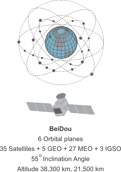
Click here to see a text description.
BeiDou
- 6 Orbital Planes
- 35 Satellites + 5 GEO + 27 MEO + 3 IGSO
- 55 degree Inclination angle
- Altitude 38,300 km, 21,500 km
BEIDOU
The fourth GNSS system, joining those undertaken by the United States—GPS, Russia—GLONASS and Europe—Galileo, will be the Chinese-BeiDou. The system is named after the Big Dipper.
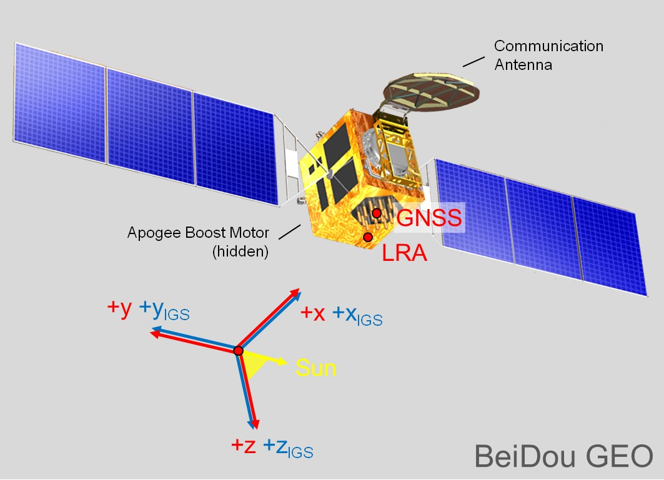
BeiDou GEO Satellite
Source: http://mgex.igs.org/IGS_MGEX_Status_BDS.html
The first generation of the system is known as BeiDou-1. It is a regional satellite navigation system that services a portion of the Earth from 70°E longitude to 140°E longitude and from latitude 5°N to 55°N. It relies on 3 satellites with 1 backup. The first satellites were launched into geostationary (GEO) orbits in 2000; BeiDou-1A at 140º E longitude and BeiDou-1B 80º E longitude. A third satellite, BeiDou-1C joined them 3 years later at110.5º E longitude. With the launch of the fourth, BeiDou-1D in 2007 the first BeiDou-1 system was operational, regionally.
Beidou-2 (aka Compass) is the second generation of the BeiDou Navigation Satellite System (BDS). In 2007, Xinhua, the government news agency, announced that the People’s Republic of China National Space Administration would launch two more GEO satellites to open the way to a global Chinese Satellite Navigation system to replace the regional BeiDou-1.
The first BeiDou-2 satellite, a medium Earth orbit (MEO) satellite named Compass-M1, was launched into a circular orbit at 21,500 km at an inclination of 55.5º. Similar satellites followed; and between 2007 and 2012, there were 5 MEO satellites with sequential names from Compass-M1 to M6 (without an M2) launched. During the period from 2009 to 2012, the 6 GEO BeiDou-2 satellites with sequential names from Compass-G1 to G6 were launched. Their positions are at 58.75°E longitude (G5), 80.0°E longitude (G6), 110.5°E longitude (G3), 140.0°E longitude (G1), 160.0°E longitude (G4). The G2 satellite is inactive.
From 2010 to 2011, the 5 high Earth orbit (HEO) BeiDou-2 satellites with sequential names from Compass-IGS01 to IGS05 were launched and achieved an altitude of approximately 38,000 km. The acronym IGOS means inclined geosynchronous orbit satellites. The IGS01, IGS02 and IGS03 satellite are at ~120°E. IGS04 and IGS05 are at ~95°E. All the IGSO satellites have an inclination of 55° and are arranged so that one of them is always over the Chinese region. The system began trial operations in late 2011 and followed with service to the region bounded by 55°E longitude to 180°E longitude and latitude 55°S to 55°N.

BeiDou Constelltion
Source: https://www.cosmos.esa.int/documents/13611/3707333/20200213_Ventura_Trav...
The BeiDou Constellation is operational. The constellation occupies six orbital planes. There are 44 satellites on orbit; 7 of them are geostationary satellites (GEO). 37 are non-stationary. The 37 non-stationary satellites include 27 in medium Earth orbit (MEO). 10 are orbiting at inclined geosynchronous orbits (IGSO). All the satellites will have a phased array antenna, on-board retro-reflector, a C-band horn antenna, and an S/L-band dish antenna.
BeiDou’s Signals and Services

BeiDou satellites currently transmit signals in three bands; B1 (1561.098 MHz), B1-2 (1589.742 MHz), B2 (1207.14 MHz) and B3 (1268.52). These bands overlap Galileo on E2-L1-E1, E5B, and E6 respectively. Each of the Beidou signals in these bands have an I (in-phase) and Q (quadraphase) component in quadrature with one another. BeiDou’s multiple access system is CDMA. The modulation scheme is quadraphase shift key (QPSK). The BeiDou Radio Navigation Satellite Service (RNSS) has 5 new global signals; B1C (1575.42 MHz), B1A (1575.42 MHz), B2a (1176.45 MHz), B2b (1207.14 MHz) and B3A (1268.52). These bands overlap GPS L1 and Galileo on E2-L1-E1: GPS L5 and Galileo E5a: Galileo E5b, and Galileo E6 respectively.

Radio Determination Satellite Service (RDSS) and Radio Navigation Satellite Service (RNSS).
https://onlinelibrary.wiley.com/doi/abs/10.1002/navi.291
The future BeiDou is expected to support two different kind of general services: Radio Determination Satellite Service (RDSS) and Radio Navigation Satellite Service (RNSS). The RDSS will include a short message communication (guaranteeing backward compatibility with BeiDou-1). A satellite-based 2-way short message service in China and the surrounding areas (75 -135 ° E 10 -55° N) with a power of < 3W and a capacity of more than 10 million messages/hr using 3 GEO satellites. The RDSS Characteristics will include a global message service using inter-satellite crosslinks with 10W of power and a capacity of 200,000 messages/hr using 14 MEO satellites. The Radio Navigation Satellite Service (RNSS) is very similar to that provided by GPS and Galileo and is designed to achieve a similar performance.

Satellite Based Augmentation Service (SBAS).
https://www.shangyexinzhi.com/article/2004171.html
It will also include a Satellite Based Augmentation Service (SBAS). Space Segment - three BDS-3 GEO satellites (80°E,110.5°E,140°E); Ground Segment - Operation and Control Center, Data Centers, Uplink Stations, Monitoring Stations; User Segment - BDSBAS terminals can receive RNSS navigation messages and wide area differential integrity information broadcast by GEO satellites

Click here to see a text description.
| Signals | Carrier Frequency (MHz) | Chip Rate (cps) | Multiple Access Scheme | Bandwidth (MHz) | Modulation Type | Service Type | Minimum Received Power |
|---|---|---|---|---|---|---|---|
| B1(I) | 1561.098 | 2.046 | CDMA | 4.092 | QPSK | Open | -163 dbW |
| B1(Q) | 1561.098 | 2.046 | CDMA | 4.092 | QPSK | Authorized | -163 dbW |
| B1-2(I) | 1589.742 | 2.046 | CDMA | 4.092 | QPSK | Open | -163 dbW |
| B1-2(Q) | 1589.742 | 2.046 | CDMA | 4.092 | QPSK | Authorized | -163 dbW |
| B2(I) | 1207.14 | 2.046 | CDMA | 24 | QPSK | Open | -163 dbW |
| B2(Q) | 1207.14 | 10.23 | CDMA | 24 | QPSK | Authorized | -163 dbW |
| B3 | 1268.52 | 10.23 | CDMA | 24 | QPSK | Authorized | -163 dbW |
There are two service types. The Open Service is available to the public and offers an autonomous (not differentially corrected) positional accuracy of 10m, 0.2 m/s velocity accuracy, and timing accuracy within 20 nanoseconds. The Authorized service is not available to the public. It is available to the military, specifically the militaries of China and Pakistan.
There are two navigation messages available from the BeiDou satellites. The MEO satellites and the IGSO satellites transmit the D1 NAV message, which is similar to the GPS NAV message. The D1 message has 30-bit words and 10 word subframes, i.e., 300 bits. It is broadcast at 50 bps and has adequate capacity for almanac data for 30 satellites. It also includes time offset information for UTC and other GNSS system clocks.
The GEO satellites transmit the D2 message. It also has 30-bit words and 10-word subframes but is broadcast at 500 bps. The D2 message includes pseudorange corrections to satellites in subframes 2 and 3 with enough capacity to accommodate corrections for 18 satellites. D2 has ionospheric corrections and clock corrections to other GNSS systems in subframe 5. This provides a unique service planned for the BeiDou Control/Ground Segment that has not been incorporated into other GNSS systems, a wide area differential correction available directly from the constellation rather than from a separate system. The BeiDou Ground Based Enhancement System (BGBES) network includes 150 reference stations; information from these stations provided is processed in the BeiDou Control/Ground segment and the resulting corrections are sent to the BeiDou GEO satellites. Those corrections are then broadcast by the GEO satellites via the D2 NAV message to the BeiDou user’s terminals (receivers). In other words, the GEO satellites provide satellite based augmentation (SBAS) for users in the region between 70° E. Longitude to 145° E. Longitude and 5° N. Latitude to 55° N. Latitude. While the BeiDou’s open service is said to offer positional accuracy of ~10m, the differentially corrected is expected to produce ~1m.
Within the same region, BeiDou also provides a short message service (SMS). Users are enabled to send up to 120 Chinese characters in each message.

Beidou Control Segment
http://www.satnews.com/story.php?number=1934630546
BeiDou’s Control/Ground Segment
The BeiDou Control/Ground Segment is comprised of a Master Control Station (MCS), two Upload Stations (US) and a network of 30 widely distributed Monitoring Stations (MS). Similar to the control of other GNSS constellations, the MCS receives data from the Monitoring Stations, which track the constellation continuously. The Upload Stations send the data generated information by the MCS to the satellites.
The MCS is responsible for the operational control of the system, including orbit determination, navigation messages, and ephemerides which are based on the China Geodetic Coordinate System 2000 (CGCS2000). CGCS2000 is the coordinate framework of the BeiDou System and is within a few centimeters of ITRF. The MCS also coordinates mission planning, scheduling, and time synchronization with BeiDou Time (BDT). BDT is synchronized within 100ns of UTC (NTSC) as maintained by National Time Service Center, China Academy of Science. BDT does not incorporate leap seconds. The leap second offset is broadcast by the BeiDou satellites in the navigation message. The initial epoch of BDT is 00:00:00 UTC on January 1, 2006. The offset between BDT and GPST/ GST is also to be measured and broadcasted in the navigation message.
The Quasi-Zenith Satellite System and IRNSS also known as NavIC

Click here to see a text description.
Quasi-Zenith Satellite System (QZSS)
- 3 Orbital Planes
- 3 Satellites
- ~40 degree inclination angle
- Altitude
The first demonstration satellite of the Japanese Quasi-Zenith Satellite System (QZSS), QSZ-1 was launched in 2010 by the Japan Aerospace Exploration Agency (JAXA) from the Tanegashima Space Center. It is expected to have a design life of 10 years. The system is nicknamed Michibiki, meaning guide. Three more satellites were launched in phase two in 2017. They include 2 additional quasi-zenith satellites, QZ-2 and QZ-3 and 1 geostationary satellite, QZ-4 which is on orbit at the equator. The 4 satellite constellation is planned to increase to 7 satellites in the future.

QZSS is intended to provide satellites in highly elliptical orbits (HEO) that are inclined and geosynchronous. The orbits are designed, so the satellites will always be available at high elevation angles that are almost directly overhead in Japan, Oceania and East Asia. This is the origin of the term quasi-zenith. They orbit at ~32000 km to ~40000km. And all follow the same asymmetrical figure-8 ground track in the region. QZSS is primarily a multi-satellite regional augmentation system (SBAS). The system offers both Sub-meter Level Augmentation Service (SLAS) and Centimeter Level Augmentation Service (CLAS). Service began November 1, 2018.

The objective is to improve satellite positioning, navigation and timing services in urban canyons and mountainous areas in the region. The system is designed to improve the positioning of GPS and Galileo receivers. The system transmits 6 signals; L1-C/A, L1C. L2C, L5, L1-SAIF and LEX. The first 4 on the list are the familiar GPS signals. The others are unique to QZSS. L1-SAIF (Submeter-class Augmentation with Integrity Function) is broadcast at the L1 frequency, 1575.42 MHz. It is interoperable with GPS and is intended to provide a sub-meter correction signal to users. Another unique signal to be broadcast by QZSS is LEX (L-band Experiment) at 1278.75 MHz. LEX is being developed to provide high accuracy positioning that is interoperable with Galileo E6. QZSS will broadcast multiple frequency signals and also provide a short message service (SMS) as does the Chinese BeiDou system. There may be user fees developed for these signals and services.
The commercial portion of the QZSS operation will be managed by Quasi-Zenith Satellite System Services Inc. (QSS). The system integration, research and development of the QZS Bus, the ground segment, etc. will be under JAXA’s control.

QZSS Control Segment
Source: https://earth.esa.int/web/eoportal/satellite-missions/q/qzss
QZSS Control/Ground Segment
The Master Control Station (MCS) develops the ephemerides, time, and navigation messages which are uploaded to the QZS satellite constellation by the main Telemetry, Tracking, and Command (TT&C) ground station in the Okinawa prefecture. Other monitoring stations on Japanese territory are at Ogasawara, Koganei, and Sarobetsu. However, there are also monitoring stations in areas governed by other nations. They are on Hawaii, Guam, Bangkok, Bangalore, and Canberra. The QZSS ground segment also includes laser ranging and tracking control stations (TCS). The main TCS station is at JAXA's Tsukuba Space Center.
The reference system for QZSS is the Japanese Satellite Navigation Geodetic System (JSG) which is quite near The International Terrestrial Reference System (ITRS). The time reference for QZSS is known as Quasi-Zenith Satellite System Time (QZSST). The system does not use leap seconds. The duration of the second in this system is the same as that in TAI (International Atomic Time).
IRNSS also known as NavIC

IRNSS Satellite
The building of the Indian Regional Navigation Satellite System (IRNSS) was authorized by the Indian government in 2006. When fully developed by the Indian Space Research Organization (ISRO), the constellation will provide position, navigation, and timing service in a region from Latitude 30° S. Latitude to 50° N. Latitude and from 30° East Longitude to 130° East Longitude. The region embraced is approximately 1500 kilometers around India. The constellation is also known as NavIC (Navigation with Indian Constellation; also, nāvik 'sailor' or 'navigator' in Sanskrit, and many other Indian languages).
The IRNSS constellation is comprised of 7 operational satellites. All the satellites will be continuously visible to the extensive Indian control segment’s 21 stations located across the country, including the Master Control Center (MCC) at Hassan, Karnataka. They are named with the prefix IRNSS-1. The constellation includes 3 of the 7 satellites in geostationary orbits at 32.5º East Longitude, 83º East Longitude and 131.5º East longitude and 4 of the 7 satellites are in geosynchronous orbits of 24,000 km apogee with an inclination of 29°. The small inclination is appropriate to the coverage of India, as the nation is located in the low latitudes. The equator crossing of 2 of the geosynchronous satellite is at 111.75º East Longitude and 2 crosses the equator at 55º East Longitude.
IRNSS-1A was launched in 2013 and is now in partial failure. IRNSS-1B and IRNSS-1C were launched in 2014. All three were launched from the Satish Dhawan Space Centre at Sriharikota, India. They carry a rubidium clocks, corner cube retro-reflectors for laser ranging and a C-band transponders. They broadcast in the L5 band (1176.45 MHz) with a bandwidth of 24 MHz and S band (2492.028 MHz) with a bandwidth of 16.5 MHz. They have a ten-year design life. IRNSS - 1D was launched in 2015. IRNSS-1E through 1G were launched in 2016. IRNSS-1H failed to make orbit. IRNSS-1I was launched in 2018.
IRNSS provides two levels of service, a public Standard Positioning Service (SPS) and an encrypted Restricted Service (RS). Both will be available on L5 and on the S band; however, the SPS signal is modulated by BPSK at I MHz and the Restricted Service will use BOC (5, 2). The navigation signals is broadcast on the S-band.


The Future

The Future
So, what is coming? Someday, there may be as many as 130 navigation satellites aloft. They will be from GPS, GLONASS, Galileo, BeiDou, QZSS, IRNSS, and perhaps others. If so, the systems will provide users with quite a variety of signals and codes. The availability of many more satellites will enable new applications in areas where their scarcity has been a hindrance. For civil users, new signals will provide more protection from interference, ability to compensate for ionospheric delays with pseudoranges, and wide-laning or even tri-laning capabilities. For military users, there will be greater anti-jam capability and security. For everybody, there will be improvement in accuracy, availability, integrity, and reliability. So, it is no surprise that there is great anticipation from a business perspective, but from a user’s point of view, the situation is not unlike the advent of GPS years ago. Much is promised, but little assured. New capabilities will be available, but exactly what and exactly when is by no means certain.
More satellites will be above an observer’s horizon. GPS and GLONASS together now provide the user with ~2 times the satellites than does GPS alone. If GPS, GLONASS, and Galileo are considered together, there will be ~3 times more. If BeiDou is added to the mix, there will be ~4 times more satellites that will be available to a user. In a sense, the more satellites, the better the performance, particularly among trees and in urban canyons, those places where signals bounce and scatter, and multipath abounds. For example, with the 6 satellites in a window available to a GPS receiver on the left side of the Urban Canyon figure below, the user may be able to increase the mask angle to decrease the multipath and still have 4 satellites to observe. Imagine if there were 12, 18, or even 24 satellites in the picture, and you can see how more satellites can mean better accessibility in restricted environments.

More satellites also mean more measurements in shorter time and that means observation periods can be shortened without degrading accuracy, in part because interference can be ameliorated more easily. With more satellites available, the time to first fix for carrier-phase receivers, the period when the receiver is solving for the integers, downloading the almanac and so forth, also known as initialization, will be shortened significantly. And fixed solution accuracy will be achieved more quickly. Today, dual-frequency carrier-phase solutions are accurate but noisy; but with the new signals available on L2C, L5, and other GNSS signals, dual-frequency solutions will be directly enhanced. While a GNSS capable receiver may offer a user improved availability and reliability, it may not necessarily offer higher accuracy than is available from GPS. However, the achievement of high accuracy more conveniently and in more places— that seems to be within reach with GNSS. It also means better ionospheric correction. Remember, the ionospheric delay is frequency dependent.
The algorithms currently necessary for the achievement of high accuracy with carrier-phase ranging may be simplified, since many of the new GNSS signals will be carrying a civilian code. Generally speaking, code correlation is a more straightforward problem than is carrier differencing. This may lead to less complicated receivers. This presents the possibility that they will be less expensive.
Also, the more diverse the maintenance of the components of GNSS, the less chance of overall system failure; the United States, Russia, the European Union, and China all have infrastructure in place to support their contribution to GNSS. Under such circumstances, simultaneous outages across the entire GNSS constellation are extremely unlikely.
Discussion
Discussion Instructions
To continue the discussion begun by this lesson, I would like to pose this question:
There is much discussion about reliance on GPS/GNSS and concern about security. It has become essential to a wide variety of critical functions. Backup for, or perhaps replacement of the system are contemplated. What are your thoughts on the subject?
To participate in the discussion, please go to the Lesson 10 Discussion Forum in Canvas. (That forum can be accessed at any time by going to the GEOG 862 course in Canvas and then looking inside the Lesson 10 module.)
Summary

Thank you very much for spending this time with me. I appreciate it. It's been a thrill, and I have enjoyed it. Thank you.
This is the conclusion of this course. Before you sign off, be sure to double-check the Lesson 10 Checklist to make sure you have completed all of the activities listed there.