Lesson 8: Real-Time Global Positioning System Surveying
The links below provide an outline of the material for this lesson. Be sure to carefully read through the entire lesson before returning to Canvas to submit your assignments.
Lesson 8 Overview
Overview
Most, not all, GPS surveying relies on the idea of differential positioning. The mode of a base or reference receiver at a known location logging data at the same time as a receiver at an unknown location together provide the fundamental information for the determination of accurate coordinates. While this basic approach remains today, the majority of GPS surveying is not done in the static post-processed mode. Post-processing is most often applied to control work. Now, the most commonly used methods utilize receivers on reference stations that provide correction signals to the end user via a data link sometimes over the Internet, radio signal, or cell phone and often in real-time.
Objectives
At the successful completion of this lesson, students should be able to:
- explain the uses of real-time kinematic GPS/GNSS and DGPS/GNSS;
- describe WAAS;
- define RTCM SC-104;
- recognize the use of the radio licensing and cell phones in RTK;
- recognize some practical RTK suggestions; and
- recognize precise point positioning PPP.
Questions?
If you have any questions now or at any point during this week, please feel free to post them to the Lesson 8 Discussion Forum. (To access the forum, return to Canvas and navigate to the Lesson 8 Discussion Forum in the Lesson 8 module.) While you are there, feel free to post your own responses if you, too, are able to help out a classmate.
Checklist
Lesson 8 is one week in length. (See the Calendar in Canvas for specific due dates.) To finish this lesson, you must complete the activities listed below. You may find it useful to print this page out first so that you can follow along with the directions.
| Step | Activity | Access/Directions |
|---|---|---|
| 1 | Read the lesson Overview and Checklist. | You are in the Lesson 8 online content now. The Overview page is previous to this page, and you are on the Checklist page right now. |
| 2 | Read the Chapter 7 in GPS for Land Surveyors. | Text |
| 3 | Read the lecture material for this lesson. | You are currently on the Checklist page. Click on the links at the bottom of the page to continue to the next page, to return to the previous page, or to go to the top of the lesson. You can also navigate the lecture material via the links in the Lessons menu. |
| 4 | Participate in the Discussion. | To participate in the discussion, please go to the Lesson 8 Discussion Forum in Canvas. (That forum can be accessed at any time by going to the GEOG 862 course in Canvas and then looking inside the Lesson 8 module.) |
| 5 | Read lesson Summary. | You are in the Lesson 8 online content now. Click on the "Next Page" link to access the Summary. |
Real-Time Kinematic and Differential GPS

Errors in satellite clocks, imperfect orbits, the trip through the layers of the atmosphere, and many other sources contribute inaccuracies to GPS/GNSS signals by the time they reach a receiver. Real-time positioning is built on the idea that, with the important exceptions of multipath and receiver noise, these GPS/GNSS error sources are correlated. Nevertheless, the errors are variable, so the best to way to correct them is to monitor them as they happen. A good way to do this is to set up a GPS/GNSS receiver on a station whose position is known exactly, a base station. This base station receiver’s computer can calculate its position from satellite data, compare that position with its actual known position, and find the difference. The resulting error corrections can be communicated from the base to the rover over a data link. It works well, as long as the base station monitors them all the time, at least all the time the rover receiver or receivers are working. While this is happening, the rovers move from place to place collecting the points whose positions you want to know relative to the base station, which is the real objective after all.

Radial GPS/GNSS
Such real-time surveying is essentially radial. There are advantages to the approach. The advantage is a large number of positions can be established in a short amount of time with little or no planning. The disadvantage is that there is little or no redundancy in positions derived, each of the baselines originates from the same control station. If there's an error in one of these radial baselines, it would be tough to catch it because there's no real redundancy. Redundancy can be incorporated, but it requires repetition of the observations so each baseline is determined with more than one GPS/GNSS constellation. One way to do it is to occupy the project points, the unknown positions, successively, with more than one rover. It is best if these successive occupations are separated by 4 hours and not more than 8 hours, so the satellite constellation can reach a significantly different configuration. However, a re-occupation as little as 1/2 hour later can yield good results. Another way is to move the base to another known point. Then, if you have vectors from another base into these points, you have a check. This approach allows a solution to be available from two separate control stations. Obviously, this can be done with re-occupation of the project points after one base station has been moved to a new control point, or a two base stations can be up and running from the very outset and throughout of the work as would be the case using two CORS stations. An advantage to a continuously operating reference station network is that since those bases are operating simultaneously and all the time, it's possible to download the positions from more than one base and process your new position based on these continuously operating reference stations and have some redundancy.
A more convenient but less desirable approach is to do a second occupation almost immediately after the first. The roving receiver’s antenna is blocked or tilted until the lock on the satellites is interrupted. It is then re-oriented on the unknown position a second time for the repeat solution. This does offer a second solution, but from virtually the same constellation.
Project points that are near one another but far from the control station should be directly connected with a baseline to maintain the integrity of the survey. Finally, if the base receiver loses lock and it goes unnoticed, it will completely defeat the radial survey for the time it is down.
Differential GPS (DGPS)

The term DGPS is sometimes used to refer to differential GPS that is based on pseudoranges, aka code phase. Even though the accuracy of code phase applications was given a boost with the elimination of Selective Availability (SA) in May 2000, consistent accuracy better than the 2-5 meter range still requires reduction of the effect of correlated ephemeris and atmospheric errors by differential corrections. Though the corrections could be applied in post-processing services that supply these corrections, most often operate in real-time. In such an operation, pseudorange based versions can offer meter- or even submeter results. Usually, pseudorange corrections are broadcast from the base to the rover or rovers for each satellite in the visible constellation. Rovers with an appropriate input/output (I/O) port can receive the correction signal and calculate coordinates. The real-time signal comes to the receiver over a data link. It can originate at a project specific base station, or it can come to the user through a service, of which there are various categories. Some are open to all users, and some are by subscription only. Coverage depends on the spacing of the beacons, aka transmitting base stations, their power, interference, and so forth. Some systems require two-way, some one-way, communication with the base stations. Radio systems, geostationary satellites, low-earth-orbiting satellites and cellular phones are some of the options available for two-way data communication. In any case, most of the wide variety of DGPS services were not originally set up to augment surveying and mapping applications of GPS; they were established to aid GPS navigation.
Real-Time Kinematic

The Correction Signal
The agreed upon protocol for communication between base stations and rovers was first designed for used in marine navigation by an organization known as the Radio Technical Commission for Maritime Services (RTCM). RTCM is an independent not-for-profit organization that is supported by an international membership that includes both governmental and non-governmental institutions. Its goals are educational, scientific, and professional. Toward those ends, it provides information on maritime radio-navigation and radio communication policies and associated regulations to its members. It is also involved in technical standards development.
In 1985, the RTCM Special Committee (SC-104) created a standard that is still more used than any proprietary formats that have come along since. RTCM is open. In other words, it is a general-purpose format and is not restricted to a particular receiver type. The message augments the information from the satellites. It was originally designed to accommodate a slow GPS data rate with a configuration somewhat similar to the navigation message. The data format has evolved since its inception. For example, RTCM 2.0 supported GPS code only. However, when it became clear in 1994 that including carrier phase information in the message could improve the accuracy of the system, RTCM Special Committee 104 added four new message types to Version 2.1 to fulfill the needs of RTK. RTCM 2.1 supported both code and phase correction, but still GPS only. Version 2.2 became available in 1998. RTCM 2.2 added support for GLONASS, and version 2.3 included antenna corrections, and the changes continued. In 2007, the Radio Technical Commission for Maritime Services Special Committee 104 published its Version 3. RTCM 3.0 utilizes a more efficient message structure than its predecessors, which proves beneficial in the RTK data heavy real-time communications between a base and a rover. Version 3.0 still provides both GPS and GLONASS code and carrier messages, antenna and system parameters. RTCM 3.1 adds a network correction message and version 3.2 announced in 2013 introduces a feature known as Multiple Signal Messages (MSM). MSM includes the capability to handle the European Galileo and the Chinese Beidou GNSS systems in the RTCM protocol.
Satellite Based Augmentation

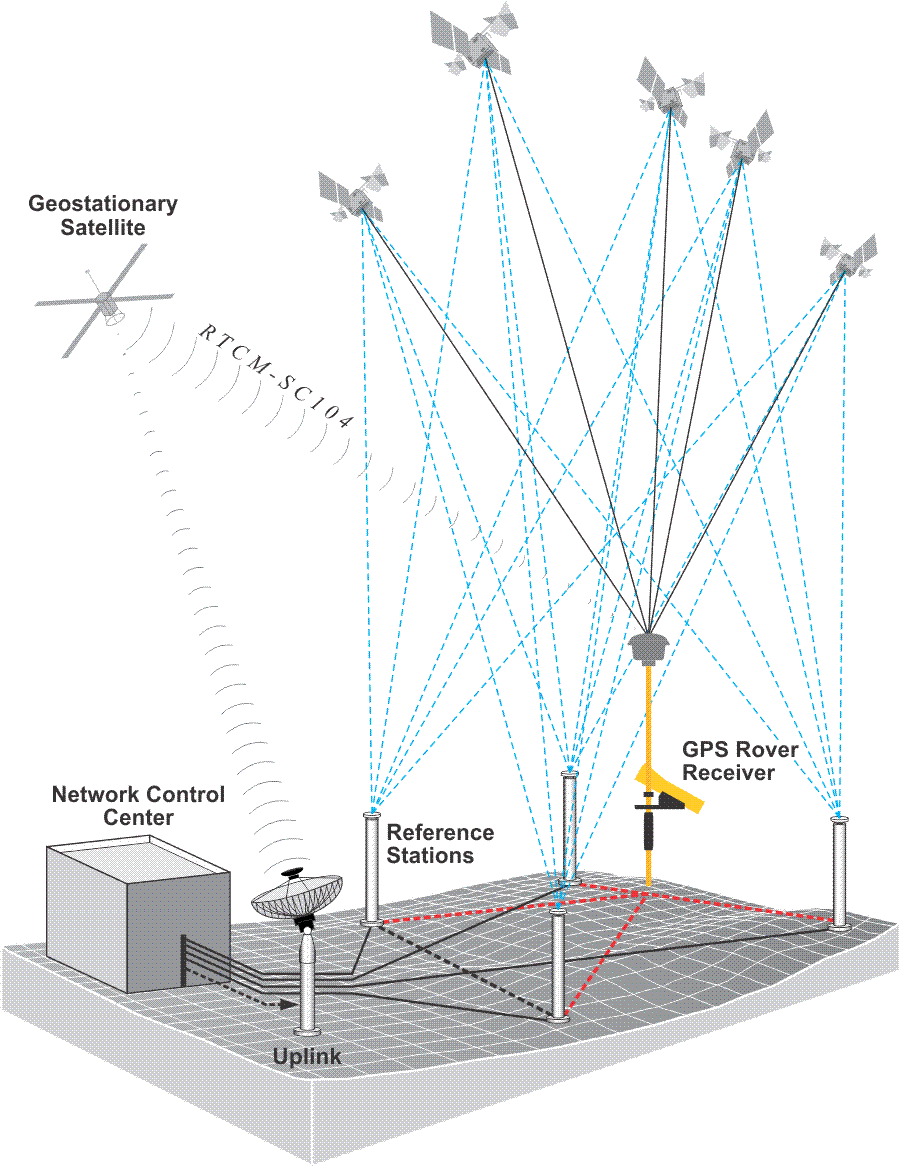
The correlation between most of the GPS biases becomes weaker as the rover gets farther from the base. The term Local Area Differential GPS (LADGPS), is used when the baselines from a single base station to the roving receivers using the service are less than a couple of hundred kilometers. The term Wide Area Differential GPS (WADGPS) is used when the service uses a network of base stations and distributes correction over a larger area, an area that may even be continental in scope. Many bases operating together provide a means by which the information from several of them can be combined to send a normalized or averaged correction tailored to the rover’s geographical position within the system. Some use satellites to provide the data link between the service provider and the subscribers. Such a system depends on the network of base stations on the ground receiving signals from the GPS/GNSS constellation and then streaming that data to a central computer at a control center. Then the corrections are calculated and uploaded to a geo-stationary communication satellite. You see that on the left with the yellow arrow going up as an upload to a satellite, Inmarsat. The satellite then broadcasts these correction signals to the service’s subscribers (i.e. aircraft).
NDGPS Coverage and Wide Area Augmentation System (WAAS)

NDGPS
Both the U.S. Coast Guard (USCG) and the Canadian Coast Guard (CCG) instituted DGPS services to facilitate harbor entrances, ocean mapping, and marine traffic control as well as navigation in inland waterways. Their system base stations beacons broadcast GPS corrections along major rivers, major lakes, the east coast, and the west coast. The sites use marine beacon frequencies of 255 to 325 kHz, which has the advantage of long range propagation that can be several hundreds of kilometers. Access to the broadcasts is free, and over recent years the service has become very popular outside of its maritime applications, particularly among farmers engaged in GPS aided precision agriculture. Therefore, the system has been extended beyond waterways across the continental U.S. and is now known as the Nationwide DGPS (NDGPS).
Wide Area Augmentation System, WAAS
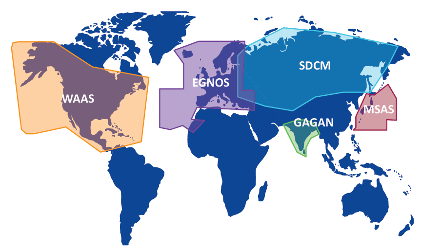
Another U.S. DGPS service initiated in 1994 cooperatively by the Department of Transportation and the Federal Aviation Administration (FAA) is known as WAAS (see figure above). It is available to users with GPS receivers equipped to receive it. The signal is free. The official horizontal accuracy is 7.6 m, but it often delivers better. It utilizes both satellite-based augmentation systems, also known as SBAS, and ground-based augmentations and was initially designed to assist aerial navigation from takeoff, en route through landing. Reference stations at known locations are the bases on the ground. They send their data via processing sites to three Ground Earth Master Stations that upload differential corrections and time to three commercial geo-stationary satellites devoted to transmission of GPS differential corrections to users on the ground. DGPS requires that all receivers collect pseudoranges from the same constellation of satellites. It is vital that the errors corrected by the base station are common to the rovers. The rover must share its selection of satellites with the base station.
The European Geostationary Navigation Overlay Service (EGNOS) has a similar configuration as does the Japanese Multi-functional Satellite Augmentation System (MSAS); India's GPS And Geo-Augmented Navigation (GAGAN) system and Russia's System for DIfferential Corrections and Monitoring (SDCM).
Latency and GIS

Latency
It takes some time for the base station to calculate corrections, and it takes some time for it to put the data into packets in the correct format and transmit them. Then the data makes its way from the base station to the rover over the data link. It is decoded and must go through the rover’s software. The time this takes is called the latency of the communication between the base station and the rover. It can be as little as a quarter of a second or as long as a couple of seconds. And since the base station's corrections are only accurate for the moment they were created, the base station must send a range rate correction along with them. Using this rate correction, the rover can back date the correction to match the moment it made that same observation.
Identical Constellation
DGPS requires that all receivers collect pseudoranges from the same constellation of satellites. It is vital that the errors corrected by the base station are common to the rovers. The rover must share its selection of satellites with the base station; otherwise it would be necessary to create differential corrections for all the combinations of all the available satellites. That could get unmanageable in a hurry, for example, with just four satellites above the observer’s horizon, there can be more than 80 such combinations.
GIS Applications for DGPS
Aerial navigation, marine navigation, agriculture, vehicle tracking, and construction utilize DGPS. DGPS is also useful in land and hydrographic surveying, but perhaps the fastest growing application for DGPS is in data collection, data updating, and even in-field mapping for Geographic Information Systems (GIS). GIS data has long been captured from paper records, such as digitizing and scanning paper maps. Photogrammetry, remote sensing, and conventional surveying have also been data sources for GIS. More recently, data collected in the field with DGPS has become significant in GIS.
GIS data collection with DGPS requires the integration of the position of features of interest and relevant attribute information about those features. In GIS, it is frequently important to return to a particular site or feature to perform inspections or maintenance. DGPS with real-time correction makes it convenient to load the position or positions of features into a data logger, and navigate back to the vicinity. But to make such applications feasible, a GIS must be kept current. It must be maintained. A receiver configuration including real-time DGPS, sufficient data storage, and graphic display allows verification and updating of existing information.
DGPS allows the immediate attribution and validation in the field, with accurate and efficient recording of position. In the past, many GIS mapping efforts have often relied on ties to street centerlines, curb-lines, railroads, and so forth. Such dependencies can be destroyed by demolition or new construction. DGPS can provide reliable positioning even if the landscape has changed. And its data can be integrated with other technologies, such as laser range-finders, and so forth, in environments where DGPS is not ideally suited to the situation. Finally, loading GPS/GNSS data into a GIS platform does not require manual intervention. GPS/GNSS data processing can be automated; the results are digital and can pass into a GIS format without redundant effort, reducing the chance for errors.
RTK and the Federal Communications Commission (FCC)
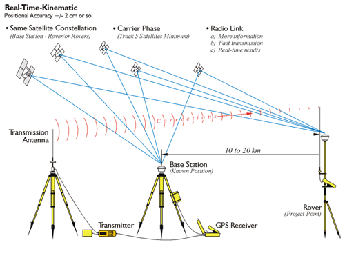
Kinematic surveying, also known as stop-and-go kinematic surveying, is not new. The original kinematic GPS/GNSS innovator, Dr. Benjamin Remondi, developed the idea in the mid-1980s. Real-Time Kinematic, RTK, is a method that provides positional accuracy nearly as good as static carrier phase positioning, but faster. RTK accomplishes positioning in real-time shown in the figure above. It involves the use of at least one stationary reference receiver, the base station, and at least one moving receiver, the rover. All the receivers involved observe the same satellites simultaneously. The base receivers are stationary on control points. The rovers move from project point to project point across, stopping momentarily at each new point, usually briefly. The collected data provides vectors between themselves and the base receivers in real-time. RTK has become routine in development and engineering surveys where the distance between the base and roving receivers can most often be measured in thousands of feet. When compared with the other relative positioning methods, there is little question that the very short sessions of the real-time kinematic method can produce the largest number of positions in the least amount of time. The remarkable thing is that this technique can do so with only slight degradation in the accuracy of the work. Real-time kinematic is done by carrier phase ranging. It must track five satellites minimum. The reason for the five satellites is basically to have one spare so that you're absolutely sure that you will have a position all the time. The base station is set up on a known point there is a transmission antenna associated with it through which a radio transmitter sends corrections to a rover. The baselines are typically at 10 to 20 kilometers, which is considerably shorter than DGPS's effective range.
Fixing the Integer Ambiguity in RTK
RTK receivers can be single- or multi-frequency receivers with GPS/GNSS antennas, but multi-frequency receivers are usual because RTK relies on carrier phase observations corrected in real-time. In other words, it depends on the fixing of the integer cycle ambiguity, and that is most efficiently accomplished with a multi-frequency GPS/GNSS receiver capable of making both carrier phase and precise pseudorange measurements. Here is one way it can be done. A search area is defined in the volume of the possible solutions, but that group is narrowed down quite a bit by using pseudoranges. If the number of integer combinations to be tested is greatly reduced with precise pseudoranges, the search can be quickly limited. The possible solutions in that volume are tested statistically, according to a minimal variance criterion, and the best one is found. This candidate is verified, that is, compared with the second best candidate. The process can take less than 10 seconds under the best circumstances where the receivers are tracking a large constellation of satellites, the PDOP is small, the receivers are multi-frequency, there is no multipath, and the receiver noise is low. This technique relies on multi-frequency information. Observations are combined into a wide lane, which has an ambiguity of about 86 cm, and the integer ambiguity is solved in a first pass. This information is used to determine the kinematic solution on L1. Therefore, it is a good idea to restrict RTK to situations where there is good correlation of atmospheric biases at both ends of the baseline. In other words, RTK is best used when the distance between the base and rover is between 10 km and 20 km, 6 miles and 12 miles, but usually less. It is fortunate that GPS/GNSS receivers with virtually instantaneous carrier phase-based positioning are available. These techniques of integer cycle ambiguity resolution, validation, and quality control are being further improved to apply to GNSS data processing.
![]()
RTK also requires a real-time wireless connection be maintained between the base station and the rover. The radio receiving antennas for the rovers will either be built into the GPS/GNSS antenna or be present as separate units. It is usual that the radio antenna for the data transmitter and the rover are omnidirectional whip antennas; however, at the base it is usually on a separate mast and has a higher gain than those at the rovers. The position of the transmitting antenna affects the performance of the system significantly. It is usually best to place the transmitter antenna as high as is practical for maximum coverage, and the longer the antenna, the better its transmission characteristics. It is also best if the base station occupies a control station that has no overhead obstructions, is unlikely to be affected by multipath, and is somewhat away from the action if the work is on a construction site. It is also best if the base station is within line of sight of the rovers. If line of sight is not practical, as little obstruction as possible along the radio link is best.
The data radio transmitter consists of an antenna, a radio modulator, and an amplifier. The modulator converts the correction data into a radio signal. The amplifier increases the signal’s power, which determines how far the information can travel. Well, not entirely; the terrain and the height of the antenna have something to do with it too. RTK work requires a great deal of information be successfully communicated from the base station to the receivers. The base station transmitter ought to be VHF, UHF, or spread spectrum-frequency hopping or direct to have sufficient capacity to handle the load. UHF spread spectrum radio modems are the most popular for DGPS and RTK applications. The typical gain on the antenna at the base is 6 dB. But while DGPS operations may need no more than 200 bits-per-second (bps), updated every 10 seconds or so, RTK requires at least 2400 bps updated about every 1/2 second or less. Like the power of the transmission, the speed of the link between the base and rover, the data rate, can be a limiting factor in RTK performance.
As mentioned earlier, RTK is at its best when the distance between the base station and the rovers is 6-12 miles or less. However, the baseline's length may be further limited by the effective range of the radio data link. In areas with high radio traffic, it can be difficult to find an open channel. It is remarkable how often the interference emanates from other surveyors in the area doing RTK as well. Most radios connected to RTK GPS/GNSS surveying equipment operate between UHF 400-475 MHz or VHF 170-220 MHz, and emergency voice communications also tend to operate in this same range, which can present problems from time to time. That is why most radio data transmitters used in RTK allow the user several frequency options within the legal range. The usual data link configuration operates at 4800 baud or faster. The units communicate with each other along a direct line-of-sight. The transmitter at the base station is usually the larger and more powerful of the two radios. However, the highest wattage radios, 35 Watts or so, cannot be legally operated in some countries. Lower power radios, from 1/2 W to 2 W, are sometimes used in such circumstances. The radio at the rover has usually lower power and is smaller. The Federal Communications Commission (FCC) is concerned with some RTK GPS/GNSS operations interfering with other radio signals, particularly voice communications. It is important for GPS/GNSS surveyors to know that voice communications have priority over data communications.
The FCC requires cooperation among licensees that share frequencies. Interference should be minimized. For example, it is wise to avoid the most typical community voice repeater frequencies. They usually occur between 455-460 MHz and 465-470 MHz. Part 90 of the Code of Federal Regulations, 47 CFR 90, contains the complete text of the FCC Rules including the requirements for licensure of radio spectrum for private land mobile use. The FCC does require application be made for licensing a radio transmitter. Fortunately, when the transmitter and rover receivers required for RTK operations are bought simultaneously, radio licensing and frequency selection are often arranged by the GPS/GNSS selling agent. Nevertheless, it is important that surveyors do not operate a transmitter without a proper license. Please remember that the FCC can levy fines for several thousand dollars for each day of illegal operation. More can be learned by consulting the FCC Wireless Fee Filing Guide. There are also other international and national bodies that govern frequencies and authorize the use of signals elsewhere in the world. In some areas, certain bands are designated for public use, and no special permission is required. For example, in Europe, it is possible to use the 2.4 GHz band for spread spectrum communication without special authorization with certain power limitations. Here in the United States, the band for spread spectrum communication is 900 MHz. It is vital, of course, that the rover and the base station are tuned to the same frequency for successful communication. The receiver also has an antenna and a demodulator. The demodulator converts the signal back to an intelligible form for the rover’s receiver. The data signal from the base station can be weakened or lost at the rover from reflection, refraction, atmospheric anomalies, or even being too close. A rover that is too close to the transmitter may be overloaded and not receive the signal properly, and, of course, even under the best circumstances, the signal will fade as the distance between the transmitter and the rover grows too large.
In RTK, generally speaking, the more satellites that are available the faster the integer ambiguities will be resolved. A multi-frequency receiver is a real benefit in doing RTK. Using a multi-frequency receiver instead of a single-frequency receiver is almost as if there were one and a half more satellites available to the observer. It is best to set up the base station over a known position first, before configuring the rover. After the tripod and tribrach are level and over the point, attach the GPS/GNSS antenna to the tribrach and, if possible, check the centering again. Set up the base station transmitter in a sheltered location at least 10 feet from the GPS/GNSS antenna, and close to the radio transmitter’s antenna. It is best if the airflow of the base station transmitter’s cooling fan is not restricted. The radio transmitting antenna is often mounted on a range pole attached to a tripod. Set the radio transmitting antenna as far as possible from obstructions and as high as stability will allow. Be certain there are no power lines in the vicinity before setting up the radio transmitting antenna to eliminate the danger of electrocution. The base station transmitter’s power is usually provided by a deep-cycle battery. Even though the attendant power cable is usually equipped with a fuse, it is best to be careful to not reverse the polarity when connecting it to the battery. It is also best to have the base station transmitter properly grounded, and avoid bending or kinking any cables. After connecting the base station receiver to the GPS/GNSS antenna, to the battery and the data collector, if necessary, carefully measure the GPS/GNSS antenna height. This measurement is often the source of avoidable error, both at the base station and the rovers. Many surveyors measure the height of the GPS/GNSS antenna to more than one place on the antenna, and it is often measured in both meters and feet for additional assurance. Select a channel on the base station transmitter that is not in use, and be sure to note the channel used so that it may be set correctly on the rovers as well. When the RTK work is done, it is best to review the collected data from the data logger. Whether or not fixed height rods have been used, it is a good idea to check the antenna heights. Incorrect antenna heights are a very common mistake. Another bulwark against blunders is the comparison of different observations of the same stations. If large discrepancies arise, there is an obvious difficulty. Along the same line, it is worthwhile to check for discrepancies in the base station coordinates. Clearly, if the base coordinate is wrong, the work created from that base is also wrong. Finally, look at the residuals of the final coordinates to be sure they are within reasonable limits. Remember that multipath and signal attenuation can pass by the observer without notice during the observations, but will likely affect the residuals of the positions where they occur.
It is certainly possible to perform a differential survey in which the position of the base station is either unknown or based on an assumed coordinate at the time of the survey. However, unless only relative coordinates are desired, the absolute position of the base station must be known or determined in the end. In other words, the base station must occupy a control position, even if that control is established later. There is an alternative to the radio link method of RTK; the corrections can be carried to the rover using a cell phone. The cell phone connection does tend to ameliorate the signal interruptions that can occur over the radio link, and it offers a somewhat wider effective range in some circumstances. The use of cell phones in this regard is also a characteristic of Real-Time Network (RTN) solutions, but connectivity is require, of course..

The Vertical Component in RTK
The output of RTK can appear to be somewhat similar to that of optical surveying with an electronic distance measuring (EDM) and a level. Nevertheless, it is not a good idea to consider the methods equivalent. RTK offers some advantages and some disadvantages when compared with more conventional methods. For example, RTK can be much more productive since it is available 24 hours a day and is not really affected by weather conditions. However, when it comes to the vertical component of surveying, RTK and the level are certainly not equal. GPS/GNSS can be used to measure the differences in ellipsoidal height between points with good accuracy. However, unlike a level—unaided GPS/GNSS cannot be used to measure differences in orthometric height. Orthometric elevations are not directly available from the geocentric position vectors derived from GPS/GNSS measurements. The accuracy of orthometric heights in GPS/GNSS is dependent on the veracity of the geoidal model used and the care with which it is applied. Fortunately, ever improving geoid models have been, and still are, available from NGS. Since geoidal heights can be derived from these models, and ellipsoidal heights are available from GPS/GNSS, it is certainly feasible to calculate orthometric heights, especially when a geoid model is on-board the RTK systems. However, it is important to remember that without a geoid model RTK will only provide differences in ellipsoid heights between the base station and the rovers. It is not a good idea to presume that the surface of the ellipsoid is sufficiently parallel to the surface of the geoid and ignore the deviation between the two. They may depart from one another as much as a meter, approximately 3 feet, in 4 or 5 kilometers, 2.5 to 3 miles.
Real Time Networks

There is no question that RTK dominates the GPS/GNSS surveying applications. It is applicable to much of engineering, surveying, air-navigation, mineral exploration, machine control, hydrography, and a myriad of other areas that require high accuracy in real-time. However, the requirements of setting up a GPS/GNSS reference station on a known position, the establishment of a radio frequency transmitter and all attendant components before a single measurement can be made are both awkward and expensive. This, along with the baseline limitation of short baselines, 10 to 20 kilometers, usually shorter, has made RTK both more cumbersome and less flexible than most surveyors prefer.

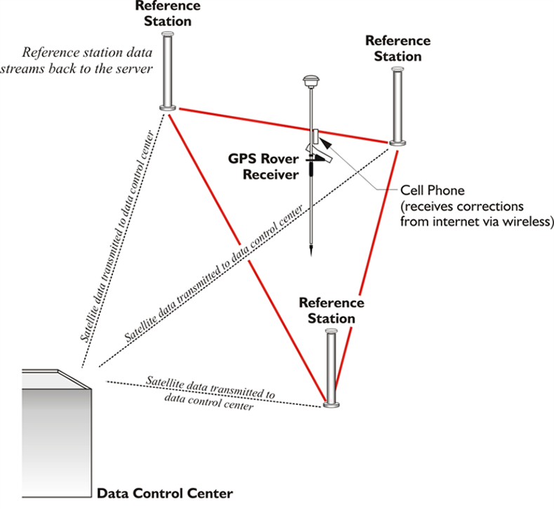
In an effort to alleviate these difficulties, services have arisen around the world to provide RTCM real-time corrections to surveyors by a different means. Real-Time Networks, RTN, have been implemented by both governments and commercial interests. The services are sometimes free and sometimes require subscription or the payment of a fee before the surveyor can access the broadcast corrections over a data link via a modem such as a cell phone or some other device. Nevertheless, there are definite advantages, including the elimination of individual base station preparation and the measurement of longer baselines without rapid degradation of the results. These benefits are accomplished by the services gleaning corrections from a whole network of Continuously Operating Reference Stations, CORS, rather than just a single base. In this way, quality control is facilitated by the ability to check corrections from one CORS with those generated from another, and should a CORS go off-line or give incorrect values, other CORS in the network can take up the slack with little accuracy loss.
The central idea underlying RTN differential corrections is the combination of observations from several CORS at known positions used to derive a model of an entire region. So, rather than being considered as isolated beacons with each covering its own segregated area, the CORS are united into a network. The data from the network can then be used to produce a virtual model of the area of interest. From this model, distance-dependent biases such as ionospheric, tropospheric, and orbit errors can be calculated. Once the roving receiver’s place within that network is established, it is possible to predict the errors at that position with a high degree of certainty. Not only can the CORS network be used to model errors in a region more correctly, but the multi-base solution also can improve redundancy. Solving several baselines that converge on a project point simultaneously rather than relying on just one from typical RTK adds more certainty to the resulting coordinate.
Implementing an RTN requires data management and communication. The information from the CORS must be communicated to the central master control station, where all the calculations are done. Their raw measurement data, orbits, and so forth, must be managed as they are received in real-time from each of the CORS that make up the network. Along with the modeling of the distance-dependent errors, all the integer ambiguities must be fixed for each CORS in real-time. This is probably the most significant data processing difficulty required of an RTN, especially considering that there are usually large distances between the CORS. To accomplish it, postcomputed ephemerides, antenna phase center corrections, and all other available information are brought to bear on the solution such as tropospheric modeling and ionospheric modeling. Modeling is subject to variation in both space and time. For example, ionospheric and orbit biases are satellite specific, whereas tropospheric corrections can be estimated station by station. But the ionospheric, dispersive, biases change more rapidly than the tropospheric and orbit biases, which are nondispersive. Therefore, ionospheric corrections must be updated more frequently than orbit and tropospheric corrections. And while it is best to keep the modeling for ionosphere within the limited area around three or so CORS, when it comes to tropospheric and orbital modeling, the more stations used, the better.
Finally, the pseudorange and/or carrier phase residuals must be determined for the L1, L2 and/or L5 by using one of many techniques to interpolate the actual distance-dependent corrections for the surveyor’s particular position within the network. Then the subsequent corrections must be communicated to the surveyor in the field, which typically requires the transmission of a large amount of data. There is more than one way the correction can be determined for a particular position within an RTN. So far, there is no clear best method.

One approach is the creation of a position sometimes known as a Virtual Reference Station, VRS, and the attendant corrections as shown in the illustration. This approach requires a two-way communication link. Users must send their approximate positions to the master control center, usually as a string in the standard format that was defined by the National Marine Electronics Association (NMEA). The master control center returns corrections for an individual VRS, via RTCM and then the baseline processing software inside the rover calculates its position using the VRS, which seems to the receiver to be a single nearby reference station. Another method involves sending basic RTK type corrections. Or the system may broadcast raw data for all the reference stations.
RTK and DGPS Offsets


Station diagrams, observation logs, and to-reach descriptions that would rarely be necessary in real-time GPS/GNSS surveying. However, some components of static GPS/GNSS control methods are useful. One such technique is offsetting points to avoid multipath and signal attenuation.
Point Offsets
The need to offset points is prevalent in real-time GPS/GNSS. For example, an offset point must often be established far enough from the original position to avoid an obstructed signal, but close enough to prevent unacceptable positioning error. While the calculation of the allowable vertical and horizontal measurement errors can be done trigonometrically, the measurements themselves will be different than those for an offset point in a static survey. DGPS/GNSS and RTK surveying generally have lower accuracy requirements than does static control, and therefore, the establishment of the tie between an offset and the originally desired position need not be so stringent. For example, rather than the total station point and an azimuth point used in static work, a magnetic fluxgate digital compass and laser may be used to measure the tie from the offset point to the original point might be used in real-time work. It is worth noting that magnetic declination must be accommodated, and metal objects avoided when using a magnetically determined direction. Such internal compasses should be carefully checked before they are relied upon. The length of the tie may be measured by an external laser, a laser cabled directly into the GPS/GNSS receiver, or even a tape and clinometer. Lasers are much more convenient since they can be used to measure longer distances more reliably, and taping requires extra field crew members. Rather than recording the bearing and distance in a field book for postprocessing, the tie is usually stored directly in the data collector. In fact, often the receiver’s real-time processor can combine the measured distance and the direction of the sideshot with the receiver’s position and calculate the coordinate of the originally desired position.

Dynamic Lines
A technique unique to RTK and DGPS/GNSS and used especially in mobile GPS/GNSS application is the creation of dynamic lines. The GPS/GNSS receiver typically moves along a route to be mapped, logging positions at pre-determined intervals of time or distance. These points can then be joined together to create a continuous line. Obstructions along the route present a clear difficulty for this procedure. Points may be in error, or lost completely, due to multipath or signal attenuation. Also, in choosing the epoch interval, the capacity of the receiver’s memory must be considered, especially when long lines are collected. If the interval chosen is too short, the receiver’s storage capacity may be overwhelmed. If the interval is too long, important deflections along the way may be missed. Where it is impossible or unsafe to travel along the line to be collected in the field, the dynamic line may be collected with a consistent offset. This technique is especially useful in the collection of roads and railroads, where it is possible to estimate the offset with some certainty due to the constant width of the feature. It is also possible, of course, to collect routes with individual discrete points with short occupations where that approach recommends itself.
A Few RTK Procedures

As mentioned earlier, redundancy in RTK work can be achieved by occupying each newly established position twice, and it is best if the second occupation is done using a different base station than was used to control the first. If this technique is used, the control points occupied by base stations should not be too close to one another. Each time the base is set up, and before it is taken down, it is best to do a check shot on at least one known control point to verify the work. And in order to ensure that the GPS/GNSS constellation during the second occupation differs substantially from that of the first, it is best if the second occupation takes place not less than 4 hours and not more than 8 hours later than the first. Although, an interval as short as 20 minutes can have some benefit. To ensure that the centering is correct during the short occupations of RTK, it is best if a bipod is used with a fixed height rod to eliminate the possibility of incorrect height of instrument measurement corrupting the results. Concerning heights, if orthometric heights in real-time are desired, a geoidal model is required, and it is best if it is the most recent. However, please note that work retraced with a different geoidal model than was used initially will likely show vertical differences at the reoccupied points. Some rover configurations facilitate in-fill surveys. In other words, when the correction signals from the base station fail to reach the rover, the collected data is stored in the memory of the receiver for postprocessing after the work is completed.

Site Calibration
The area of interest that is the project area, covered by an RTK survey, is usually relatively small and defined. Typically, a site calibration, aka localization, is performed to prepare such a GPS/GNSS project to be done using plane coordinates. A site calibration establishes the relationship between geographical coordinates—latitude, longitude, and ellipsoidal height—with plane coordinates—northing, easting, and orthometric heights across the area. In the final analysis, the relationship is expressed in three dimensions: translation, rotation, and scale. Because of the inevitable distortion that a site calibration must model, one of the prerequisites for such localization is the enclosure of the area by the control stations that will be utilized during the work. In the horizontal plane, the method of using plane coordinates on an imaginary flat reference surface with northings and eastings, or x- and y-coordinates assumes a flat earth. That is incorrect, of course, but a viable simplification if the area is small enough and the distortion is negligible. Such local tangent planes fixed at discrete points, control points, by GPS/GNSS site calibration have been long used by land surveyors. Such systems demand little, if any, manipulation of the field observations, and once the coordinates are derived, they can be manipulated by straightforward plane trigonometry. In short, Cartesian systems are simple and convenient.
However, there are difficulties as the area grows, as was mentioned earlier. For example, typically, each of these planes has a unique local coordinate system derived from its own unique site calibration. The axes, the scale, and the rotation of each one of these individual local systems will not be the same as those elements of its neighbor’s coordinate system. Therefore, when a site calibration is done and a local flat plane coordinate system is created, it is important to keep all of the work in that system inside limits created by the control points used in its creation. In the simplest case, a single point calibration, a flat plane is brought tangent to the earth at one point, but a more typical approach is the utilization of three or four points enclosing the area of interest to be covered by the independent local coordinate system. Working outside of the limits created by those points should be avoided, as it involves working where the distortion has not been modeled. It might be said that a site calibration is a best fit of a plane onto a curved surface, in which the inevitable distortion is distributed in both the horizontal and vertical planes. The vertical aspect is particularly important. It is called upon to adjust the measured GPS/GNSS ellipsoid heights to a desired local vertical datum. Therefore, it must account for undulations in the geoid because the separation between the ellipsoid and geoidal models is seldom entirely consistent over the project area. The separation is not consistent and usually can be modeled approximately as a trend across the area of interest so that the site calibration typically produces an inclined plane in the vertical aspect. Toward that end, the set of control points used to establish the site calibration must have both geographical coordinates—latitude, longitude, and ellipsoidal height—and plane coordinates—northing, easting, and orthometric heights in the desired local system. It is best if these control points are from the National Spatial Reference System (NSRS) when possible that enclose the project and are distributed evenly around its boundary.
Precise Point Positioning

Real-time or static differential GPS and differential GNSS have long been the preferred methods of data processing for surveyors and geodesists. Typically, the differential processing technique depends on one of at least two receivers standing at a control station whose position is known, the base. It follows that the size of the positional error of the base receiver is knowable. By finding the difference between the biases at the base and the biases at the rover, the positional error at the other end of the baseline can be estimated. Through the process of differencing, corrections are generated which reduce the three-dimensional positional error at the unknown point by reducing the level of the biases there. The approach can generally provide up to sub-meter position from single frequency pseudorange observations. Differentially processed carrier phase observations can typically reach accuracies of a few centimeters. These facts have led to the construction of networks of continuously operating reference (CORS) stations on control stations and around the world to support differential processing. There are many regional networks such as the Australian Fiducial Network (AFN) administered by the Australian Surveying and Land Information Group (AUSLIG), EUREF with its EUREF Permanent Network (EPN), the Continuously Operating Reference Stations (CORS) administered by the NGS, AFREF, NAREF, SIRGAS, as well as many commercial networks, and the list is constantly growing. Some of these networks stream of real-time differential corrections to users. These real-time networks (RTNs) support the now well-known real-time kinematic (RTK) methods. The convenience of these RTNs has contributed substantially to the extraordinary expansion of relatively high accuracy GPS applications that rely on differential processing. However, there is an alternative in both real-time and post-processed work. It is known as Precise Point Positioning (PPP)
It was mentioned earlier that single point positioning can be a real-time solution using a single receiver measuring to a minimum of 4 satellites simultaneously. There is no question that this is the most common GPS solution outside of the geodesy and surveying disciplines, and it is in a sense the fulfillment of the original idea of GPS. However, its weakness is that the receiver must rely on the information it collects from the satellite’s navigation message to learn the positions of the satellites, the satellite clock offset, the ionospheric correction, etc. This data contains substantial errors. Under such circumstances, the typical pseudorange or carrier phase single point position cannot be highly accurate, but what if the positions of the satellites, the satellite clock offset, the ionospheric correction and etc., were not derived from the navigation message? There is such as source. It contains much more accurate data about the satellites' orbits and the clocks, and that enables single point positioning to achieve higher accuracy and thereby presents some advantages over differential methods. For example, the user need not establish control stations or have access to corrections from reference stations operated by others. It ameliorates the limits on the baseline lengths imposed by differential processing, and the solution is global. It can work anywhere in the world. The PPP corrections are expressed in a global reference frame, the International Terrestrial Reference Frame 2014 (ITRF2014), which offers better overall consistency than does a local or regional solution.
The International GNSS Service (IGS) is a collaboration between more than 200 organizations in more than 80 countries. As a public service, it collects and archives GPS/GNSS data from a worldwide network of more than 300 continuously operating reference stations. It formulates precise satellite ephemerides and clock solutions from these data. Up to eight IGS analysis centers are involved in the processing, and then, IGS freely distributes the results. http://www.igs.org/analysis/gps-ppp
In other words, this data allows users to process their observations using the positions of the satellites and the state of the clocks derived from the period of time the satellites were being tracked. That period of time includes the moment the user actually made the observations. Since this data reflects the precise position of the satellites and clock offsets during the actual measurements, it stands to reason that it is more precise than the broadcast ephemeris and clock corrections can be. There are several categories of this data available.
Post Processed (PP-PPP)
http://www.igs.org/analysis/gps-ppp#
The observed Ultra-Rapid ephemeris and clock data is available online 3 to 9 hours after an observation is completed. It is posted 4 times daily at 03hr, 09hr, 15hr and 21hr UTC. There is also a predicted Ultra-Rapid ephemeris and clock data that is available ahead of time and is posted at the same times as the observed Ultra-Rapid. It takes longer for the Rapid to come online, from 17 to 41 hours. It is posted each day at 17hr UTC. The Final product takes the longest of all, 12-18 days. It is posted each week on Thursday. As would be expected, the accuracy of the ephemeris and the clock data of each increment increases. This post-computed data has been available for more than a decade, and there are free PPP post-processing services. Users may upload their data files to these services websites (in the RINEX format) and be served automatically computed GNSS receiver positions at the centimeter level. The services do require that the submitted data be derived from long observation times. In the United States, the National Oceanic and Atmospheric Administration (NOAA) and, more specifically, the National Geodetic Survey (NGS) have worked with IGS to provide accurate GPS satellite ephemerides, or orbits.
Real Time Service (RTS-PPP)
Recently, near real-time information has also become available from IGS. This real-time service (RTS) was created in partnership with other organizations, specifically Natural Resources Canada (NRCan), the German Federal Agency for Cartography and Geodesy (BKG), and the European Space Agency’s Space Operations Centre in Darmstadt, Germany (ESA/ESOC). The RTS’s precise ephemeris and clock data is available on the internet every 25 seconds via an open source protocol known as the Network Transport of RTCM (NTRIP) which has been an RTCM standard for the real time collection and distribution of GNSS information since 2004. These precise satellite orbits and clocks along with code and phase observations from a dual-frequency receiver provide the data from which the PPP algorithm derives accurate positions. This is currently a GPS only service.
PPP Disadvantage
PPP currently has disadvantages. One of the most persistent is the time necessary to resolve the cycle ambiguity. The time necessary to move from a float to a fixed solution is extended because the ambiguity cannot be assumed to be an integer as it is in a differenced solution. As things stand, the convergence can take 20 minutes or more. You may recall that ionospheric delays are significantly reduced in differenced solutions. In PPP, dual-frequency receivers are needed to mitigate the ionospheric delay.
Discussion
Discussion Instructions
To continue the discussion begun by this lesson, I would like to pose this question:
Would the position on a point established by post-processed differential correction using data from an NGS Continuously Operating Reference Station (CORS) likely differ from a position on the same point established by the Real-Time Kinematic process? If so, why? If not, why not? Would the position on the same point differ from those established by the previously mentioned procedures if it was done by Precise Point Positioning? If so, why? If not, why not?
To participate in the discussion, please go to the Lesson 8 Discussion Forum in Canvas. (That forum can be accessed at any time by going to the GEOG 862 course in Canvas and then looking inside the Lesson 8 module.)
Summary
Real-TIme Kinematic
Source: GPS for Land Surveyors
There is no question that Real-Time Kinematic (RTK) dominates the GPS/GNSS surveying applications. It is applicable to much of engineering, surveying, air-navigation, mineral exploration, machine control, hydrography, and a myriad of other areas that require centimeter-level accuracy. However, the control on which it depends is typically set using static GPS/GNSS.
Real-TIme Network
Source: GPS for Land Surveyors
The pace of the development of Real-Time Networks, RTN, both by governments and commercial interests, is accelerating. The services are sometimes free and sometimes require the arrangement of a subscription or the payment of a fee before the user can access the broadcast corrections over a datalink via a modem such as a cell-phone or some other device. But the central idea at the foundation of RTN is differential correction. That is, the combination of observations from several CORS at known positions used to derive a model of an entire region still relies on the same differential ideas that we discussed near the beginning of the course. In other words, even the latest developments in satellite positioning continue to be based on the same fundamental principles.
In the next lesson, we will take a look at the changes in GPS/GNSS that will be affecting satellite positioning in the near future.
Before you go on to Lesson 9, double-check the Lesson 8 Checklist to make sure you have completed all of the activities listed there.