Lessons
Lesson 1: Materials Classification
Overview
In today’s society, virtually every segment of our everyday life is influenced by the limitations, availability, and economic considerations of the materials used. In this lesson you will be introduced to the interconnectivity of processing, structure, properties, and performance of the design, production, and utilization of materials; the role of materials scientists and engineers; and the three important criteria in materials selection. You will also be introduced to the classical classification of materials: metals, ceramics, and polymers, as well as, composites and the advanced materials classification used in modern high-tech applications.
Learning Outcomes
By the end of this lesson, you should be able to:
- Describe, with specific examples, the role of materials in human development during the Stone Age.
- List the six different property classifications of materials that determine their applicability.
- Cite the four components that are involved in the design, production, and utilization of materials, and briefly describe the interrelationships between these components.
- Describe the way in which scientists and engineers differ in their utilization of materials.
- Cite three criteria that are important in the materials selection process.
- List the three primary classifications of solid materials, and then cite the distinctive features of each.
- Briefly define smart material/system.
- Note the four types of advanced materials and, for each, its distinctive feature(s).
- Judge which material is most likely to be a promising candidate for utilization when given the primary or advanced material classifications of a list of candidate materials and one design selection criteria.
Lesson Roadmap
Lesson 1 will take us 1 week to complete. Please refer to Canvas for specific due dates.
| To Read |
Read pp 7-24 (Ch. 1) in Introduction to Materials ebook Reading on course website for Lesson 1 |
|---|---|
| To Watch | Secrets of the Terracotta Warriors |
| To Do | Lesson 1 Quiz |
Questions?
If you have general questions about the course content or structure, please post them to the General Questions and Discussion forum in Canvas. If your question is of a more personal nature, feel free to send a message to all faculty and TAs through Canvas email. We will check daily to respond.
Why Study Materials?

When materials scientist and narrator of The Secret Life of Materials videos (used in this course), Mark Miodownik, opens up the video on metal, he is at Piccadilly Circus in London, England. He marvels at how strange but wonderful it is that everything around him is man-made. This is not unique to London. A visit to the center of New York, Tokyo, Hong Kong, Beijing, Dubai, Paris, or any other 21st-century modern city would yield a similar situation. It might seem like a cliché but we are surrounded by materials. And with the range of materials available - whether it be in our professional or personal lives - we are constantly being asked to make choices about materials.
Something as routine and everyday as purchasing carbonated beverages is an example where materials choice could come into play. As we will see in the textbook, carbonated beverages can be purchased in glass, metal, or plastic containers. What factors drive manufacturers of carbonated beverages to offer their products in a range of different materials? What are the advantages and disadvantages when comparing the different materials choices for carbonated beverage containers? When selecting a material for a product there are many factors that must be taken into account, including properties, performance, and lifetime of the material; availability of raw materials; costs and energy usage in all steps of the processing; sustainability; waste disposal, etc.

Why is it important for you to understand materials? Products, devices, and components that you purchase and use are all made of materials. To select appropriate materials, and processing techniques for specific applications, you must have knowledge of the material properties and understand how the structure affects the material properties.
Throughout history, material advancement has gone hand-in-hand with societal advancements. The Stone Age, Bronze Age, and Iron Age were all significant materials and societal periods in humankind's development. One question I would pose to you: what is today's materials age? Is it the polymer age? Or perhaps we have already advanced past that one. Are we in the age of silicon, i.e., the electronic materials age? Or, are we possibly moving into a nanomaterials age? A biomaterials age? Some might suggest that we moved into the information age or the digital age. In any of these cases, it is clear that the materials and the capability of the materials underlying these technologies are integral to the current and future capabilities in these areas.
Now let us explore how deep-seated materials are in our culture by looking back at materials in antiquity.
Materials in Antiquity
Three of the greatest ‘cultural’ revolutions occurred in antiquity, and they are named for the material use associated with these revolutions. They were predominantly bloodless, occurred over a millennium, and were revolutionary, not evolutionary. These three revolutions occurred during the Neolithic Age (part of the Stone Age), the Urban Age (Bronze Age), and the Iron Age.
Before we look at the Neolithic Age revolution, let’s take a look at the pre-Neolithic Age. If we look at the human timeline below we can see that the usage of stone tools began about 3.4 million years ago. This marks the beginning of the Stone Age, which lasted until the advent of metalworking and ended at different regions from ~9000 BCE to 2000 BCE. The genus Homo emerged during the Stone Age. The earliest usage of cooking, clothes, and fire occurred during this pre-Neolithic Age, with their earliest known dates shown in the figure below. In addition to cooking, fire was particularly important from a materials point of view. Fire was used for the tempering of wood arrowheads, annealing flint, and creating charcoal before the Neolithic Age, and has been an important component of materials processes throughout all ages of human existence.
The first of these revolutions was the Neolithic Revolution, which was highlighted by the transformation from a hunter/gatherer population to a farmer/skilled artisan population. It has been argued that three steps were required for the Neolithic Revolution: 1) hunter/gatherer population increase, 2) food production in marginal areas, and 3) several communities at similar stages of development. Near the end of the Stone Age, six civilizations emerged that satisfied these requirements.

Now we will take a closer look at the materials used during the Stone Age.
Flint (and Obsidian)

Flint and obsidian were very important Stone Age materials. Commonly found with chalk and limestone, flint is a form of the mineral quartz. Obsidian is a naturally occurring volcanic glass. Both were widely used in weapons and tools. As we will learn in this lesson, flint and obsidian are classic examples of ceramics. Both are hard and can be worked to produce a sharp edge, but both materials are prone to breakage. Slowly heating flint to 150 to 260 °C (300 to 500 °F), holding the temperature there for 24 hours (annealing), and then slowly cooling it back to room temperature, can relieve internal stresses which can improve the ability to produce flint tools or weapons with a sharper cutting edge. As discussed later, since flint is typically found with chalk and limestone, it is possible that the annealing of flint led to the discovery of lime mortar.
Charcoal
Charcoal is perhaps the greatest invention of the Paleolithic (Stone) Age. Charcoal is produced by partially burning organic matter (wood, bone, etc.) while limiting the supply of oxygen. One way of producing charcoal is to pile a large amount of wood, as shown in the figure, and covering it with soil to limit the amount of oxygen feeding the fire. During the burning process, considerable water is released, and at the completion of the burn, the wood is reduced to black brittle lumps of carbon (charcoal).

Charcoal played an important role throughout the Stone Age, the Bronze Age, and the Iron Age. Why? Very few elements (noble metals and copper in very limited quantities) occur naturally in their pure form. Elements usually occur bound with other elements forming compounds, and typically occur in a mixture with other compounds. Heat is usually applied to break the compounds or melt the element to produce the raw material needed for manufacturing, such as copper and iron.
The temperatures required depend on the compounds and elements involved and can vary considerably. The temperatures obtainable by fire depend on the fuel used and the supply of air. If wood is used as the fuel in an open fire, temperatures in the fire might range from 350 to 500° C. Charcoal, being a denser and drier fuel source, can provide temperatures up to 800 °C under similar conditions. If the fire is confined, such as in a kiln or a furnace, and air is forced into the fire, it is possible to obtain even higher temperatures. For charcoal, it is possible to reach temperatures above 1000 °C.
Later, in our lesson on metals, we will see that this temperature is insufficient to melt pure iron, which is why the processing of impure iron (iron plus carbon) was developed first. Impure iron has a much lower melting temperature than pure iron. We will see that an advanced design furnace coupled with a hotter burning fuel source (coke, a form of coal) was needed to obtain pure molten iron.

Lime Mortar
When annealing flint, you can expect chalk or limestone to be present. Chalk and limestone are composed primarily of calcium carbonate (CaCO3), which is the same mineral present in hard water. It often shows up as a white residue on plumbing fixtures. If chalk or limestone is heated above 800° C (obtainable with charcoal), the gas carbon dioxide is released from the calcium carbonate leaving lime (CaO). Lime produced in this matter is referred to as quicklime or burnt lime. If water is added, this quicklime or burnt lime hydrates to form a white pasty substance known as slaked lime.
It is quite possible that an observant fire tender or cook could have noticed that, after encountering rain, this material would dry and form a hard substance. We refer to the substance as lime mortar, a type of cement. It is common to confuse the term cement with concrete. Cement is a binder or material that glues things together. Concrete, on the other hand, is a combination of cement and aggregate (sand, stone, etc.). Concrete is one example of a composite material. As we will see in this lesson a composite material is a material that is composed of two or more distinct materials in combination. Cement is the material within concrete that binds the stone and sand together.
In addition to the development of lime mortar in the Fertile Crescent, the Incas, and the Mayans independently discovered lime mortar around 5000 BCE, and it was widely used in ancient Rome and Greece around 4000 BCE.

'Plaster of Paris'
Originally, the term ‘plaster of Paris’ was coined in the 1700s to describe plaster produced from gypsum located outside of Paris. Over time, the term ‘plaster of Paris’ has become the generic term for gypsum-based plaster. Many ancient Egyptian tomb paintings are created on plaster. It is produced in a way that is similar to lime mortar, except gypsum is used in place of lime and much lower temperatures are needed. The resulting plaster is not as hard as lime mortar. Plaster vessels dating from 6000 BCE have been found from ancient Egypt.

Primary Civilizations
As mentioned before, near the end of the Stone Age, six civilizations that emerged that satisfied the requirements considered necessary for the Neolithic Revolution. If you look at the map below, you can see that there were two New World civilizations and four Old World civilizations, along with their names.

The four Old World civilizations had two very important advantages over the two New World civilizations. Namely, they were situated along great river systems and, being more numerous, had a more robust trade system in place. The great river systems were very important components in trade, but possibly of equal or greater importance was the benefit of annual flooding. Annual flooding reinvigorates farmland and, before the advent of modern farming techniques, allowed for the successful growth of crops year after year over multiple decades without the need for artificial fertilizers or crop rotation management schemes.
Two of the Old World civilizations, the Nile Valley and Mesopotamia, formed what has been called the Fertile Crescent, which is widely regarded as the birthplace of civilization. As can be seen in the figure below, both locations possessed great river systems and, due to their proximity, had well-established trade routes. At the close of the pre-Neolithic age, these two civilizations were experiencing increasing populations, had extensive food production capabilities, and had several communities at similar stages of development.

Mudbrick
The mudbrick was developed during the pre-pottery (Aceramic) Neolithic Age. Mudbricks were composed of a mixture that might have included clay, mud, loam, sand, and water mixed with a material to inhibit crumbling such as straw or rice husks. This was another example of a composite material. The ceramic material (clay, mud, loam, sand) by itself could support compressive loads but could be easily pulled apart. The second component of the composite, straw or rice husks, reinforced the first material, making it more difficult to pull the mudbrick apart. Water was used to allow the brick to be easily formed during manufacturing.
Since the early civilizations were located in warm regions with very limited timber, early bricks were sun-dried. The bricks needed to be dried before installation. Otherwise, shrinkage and cracking would occur that would destabilize the building.
Before the usage of bricks, structures were limited to wood and piling of stone. Creation of the brick unleashed creative design of buildings, and the architect was born! Clay or mud (raw material) was readily available everywhere, as was the strengthening material, straw or rice husks.
Later gravel and bitumen were used for stronger bricks. Bitumen is a naturally occurring (thermoplastic) polymer that, when heated, becomes a liquid and, when cooled, becomes solid. It is a black, tar-like substance with a consistency similar to cold molasses. Adding bitumen to bricks makes them both waterproof and much stronger. Bitumen is a mixture of hydrocarbons, which contains anywhere from 50 to thousands of carbon atoms. It is found in nature in rock asphalt, lake asphalt, and near other fossil fuels. In addition to being a structural improvement, bitumen, and crude oil sometimes found near bitumen deposits, provided fuel for brick kilns.


Pottery
The development of pottery in Mesopotamia was important for the storage of food protected from moisture and insects. Pottery takes clay and water which, in the proper proportions, form a mass that can be readily shaped. Once in the desired shape, the piece is dried to remove the water and then fired to improve mechanical stability. Clay was readily available and thus an inexpensive material to use.
Initially, unfired clay was used to line woven baskets. Although these unfired clay baskets were not particularly robust, they did provide much-needed waterproofing. Possibly, one of these early clay-lined woven baskets was discarded at the end of its usefulness. One could suppose that at some point the discarded basket was put into a fire to dispose of it. Later, in the cooled coals, someone could have discovered pottery shards and had the eureka moment where they realized that the firing of clay structures would produce pottery.
The development of pottery occurred in Mesopotamia around 7000 BCE. The invention of the pottery wheel occurred in Mesopotamia sometime between 6000 and 4000 BCE. The earliest ceramic objects (figurines) known have been found in what is now the Czech Republic and have been dated as being created between 29,000 and 25,000 BCE. The earliest pottery has been found in China and dates from around 18,000 BCE. In 10,000 BCE, Japan was using roping or coiling to produce pots. In the videos of this lesson, Secrets of the Terracotta Warriors, you will see that coiling was the method used to produce these warriors.
The Near East, at the end of the Neolithic Age (c.a. 4500 BCE), had mastered fire to produce and/or modify a number of materials. They had flint tools and weapons, buildings of mud brick with plaster finish, pottery, well-established trade routes from Mesopotamia to the Indus Valley, and a robust agrarian economy. Discussions about the Bronze Age and the Iron Age await us when we get to the lessons on metals and metal alloys. But now, let's take a look at what is materials science and engineering.

Materials Science and Engineering
In my experience in this course, students have difficulty understanding the difference between materials scientists and materials engineers. In the reading for this lesson, materials science is defined as investigating relationships between structures and properties of materials, and concern with the design/development of new materials. Materials engineering is defined as the creation of products from existing materials in the development of new materials processing techniques. I would restate the roles of material scientists and materials engineers as:
- Materials scientists study materials and create new materials.
- Materials engineers use materials and create new processes.
Now, these statements of the roles for material scientists and engineers are, of course, oversimplifications. As I think you will see in the following video (5:34) produced by the Penn State Department of Materials Science and Engineering we believe that cutting-edge materials research and development require a thorough understanding of both materials science and engineering.
To Watch
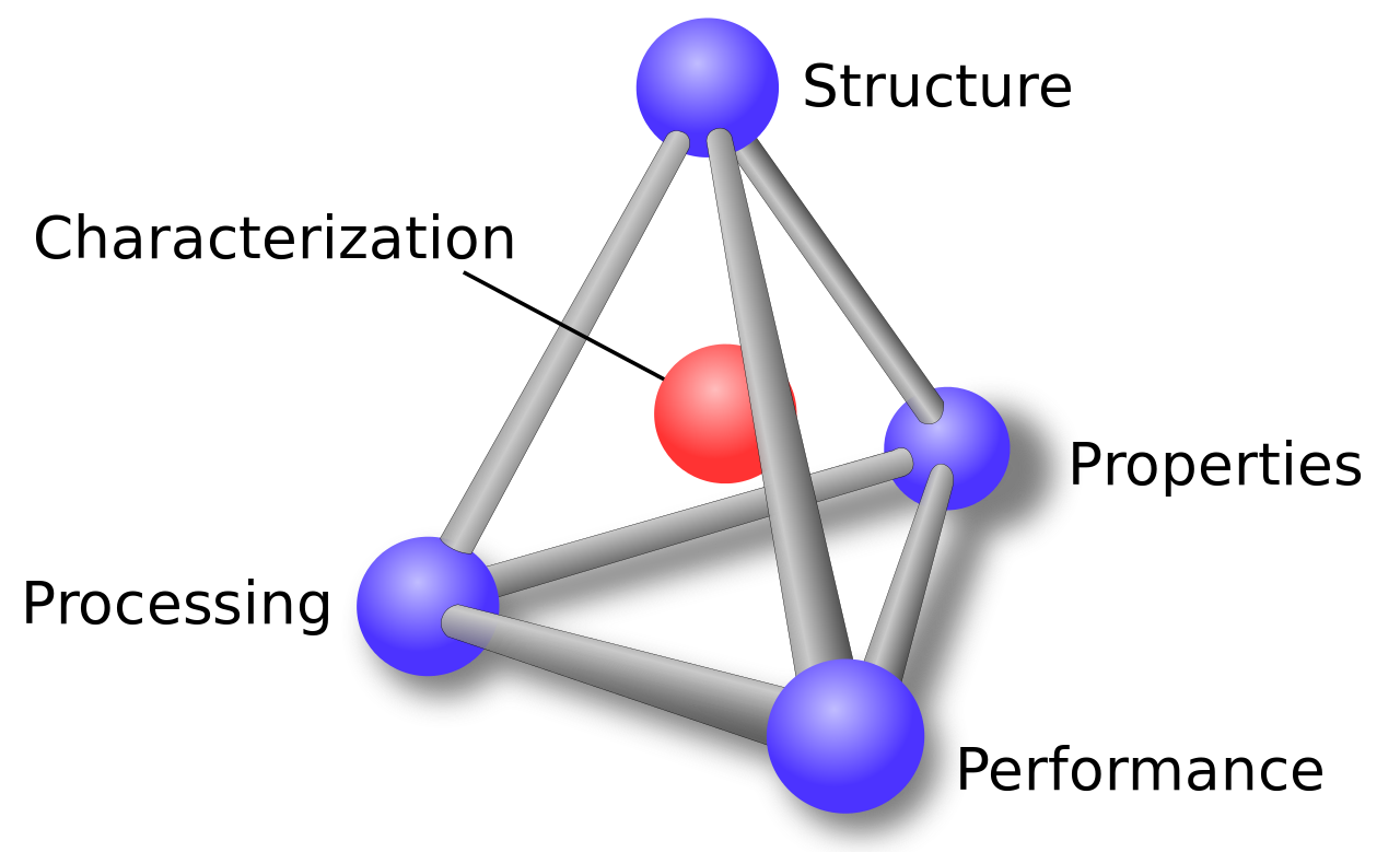
When utilizing a material, one needs to understand that the structure, properties, processing, and performance of the material are interrelated. This is represented by the materials science tetrahedron shown in the figure above. If one alters the processing, there is a direct connection with the structure, properties, and performance of the material. Adjusting any one of the factors will have varying degrees of impact on the other three factors. Characterization is the heart of the tetrahedron, signifying its role in monitoring the four components.
In this course, we will be looking at the four components (structure, properties, processing, and performance) of materials, beginning with properties. Properties of materials can be classified into six categories: mechanical, electrical, thermal, magnetic, optical, and deteriorative. We will start by looking at mechanical properties in lesson four and electrical properties in lesson 12. Unfortunately, we will not have time in this course to look at the other four properties. In lessons 3, 5, 7, and 8 we will look at the structure, both atomic and microstructure. Lesson 10 will be concerned with the processing of materials, and the performance of material will be addressed throughout the course.
Classification of Materials
Matter is composed of solid, liquid, gas, and plasma. In this course, we are going to be looking at solids which we will break down into three classical sub-classifications: metals, ceramics, and polymers.
In the reading for this lesson, representative characteristics of the three sub-classifications will be presented. In lesson three the chemical makeup and atomic structure will be further explored. The microstructure of the three classifications will be explored in their lessons.
Composites is a special additional classical sub-classification. Composites are composed of two (or more) distinct materials (metals, ceramics, and polymers) to achieve a combination of properties. Composites are introduced in this lesson in the reading and we will have a later lesson devoted to them as well. (Note: composites should not be confused with alloys. We will learn later that alloys are a mixing of a metal with other elements. In an alloy the elements are blended, they are no longer distinct components.)
Advanced materials are materials that are utilized in high-tech applications. These materials are typically enhanced or designed to be high-performance materials - many times with very specific tasks in mind.
Semiconductors are materials that can be made to switch from an insulator (off) to a conductor (on) by the application of voltage. The flow of electrons in semiconductors is somewhere between insulators, i.e., those that do not readily conduct electricity; and conductors, those materials which freely allow the flow of electrons. These materials have enabled our digital electronic age. The development of semiconductors for integrated circuits has allowed for the electronics and computer revolution that we have experienced in the last 50 years.
Nanomaterial, whose sizes typically range from 1 to 100 nanometers, are materials in which size and/or geometry can play a significant role in the dominant materials properties. In this size range, quantum mechanical effects can dominate, as well as, chemistry due to a large number of the atoms being surface atoms instead of atoms in bulk. In addition to size effects, these materials sometimes exhibit unique functionality due to their geometry. For example, gold nanoparticles can be very chemically active, unlike bulk gold. This effect is due to a large number of unsatisfied bonds on the surface of the gold nanoparticle.
Biomaterials are materials implanted into the body. In addition to performing their design function, they also have to have the ability to survive in the body (be biocompatible). The body can be a 'hostile' environment for materials. The body might attack the biomaterial as a foreign body (immune response) and the environment (wet and chemically active) in the body is typically one that leads to corrosion.
Smart materials are materials that are designed to mimic biological behavior. They are materials that, like biological systems, ‘respond to stimuli.' When determining whether a material system is utilizing a smart material, it is usually useful to identify the stimuli and the response that the material will exhibit, as well as, what biological system it is mimicking.
The readings and videos in the last two lessons of this course will explore advanced materials in more detail. Now that I have set the stage it is time for you to begin the additional reading for this lesson.
Reading Assignment
Things to consider...
When you read this chapter, use the following questions to guide your reading and always remember to keep the learning objectives listed on the overview page in mind.
- What are the materials' properties that determine materials applicability?
- What are the differences between material science scientists and engineers?
- What are the differences between metals, ceramics, and polymers?
- Does ‘best of both worlds’ apply to composites?
- Which of the materials classifications (metal, ceramics, polymers, composites, semiconductors, smart materials, biomaterials, and nanomaterials) are a distinct class of materials versus a group of materials with defining function composed of materials from distinct classes of materials?
Reading Assignment
Read pp 7-24 (Ch. 1) in Introduction to Materials ebook
Video Assignment: Secrets of the Terracotta Warriors
Now that you have read the text and thought about the questions I posed, take some time to watch this 54-minute video about determining how 8,000 terracotta warriors were manufactured in later third century BCE in China. As you watch this video, please note some of the problems that needed to be overcome and the assembly line approach that was necessary to complete everything in a two-year period.
Video Assignment
Go to Lesson 1 in Canvas and watch the Secrets of the Terracotta Warriors Video. You will be quizzed on the content of this video.
Summary and Final Tasks
Summary
Anthropologists, archeologists, and historians use the level of materials development (Stone Age, Bronze, Iron Age) to designate the stages of societal development. In today’s society, materials and materials development continue to shape development and advancement. In this lesson you were introduced to the important overarching themes of this course:
- materials scientists investigate the relationships that exist between the structures and properties of materials
- materials engineers design the structure of a material to produce a predetermined set of properties
- structure and properties are interlinked
- processing, structure, properties, and performance are interconnected
- environment, wear, and economics are three important criteria for materials selection
- classical classification of materials (metals, ceramics, and polymers, as well as, composites)
- and the advanced materials classification used in modern high-tech applications.
We will utilize the important concepts introduced in this lesson throughout the rest of the course.
Reminder - Complete all of the Lesson 1 tasks!
You have reached the end of Lesson 1! Double-check the to-do list on the Lesson 1 Overview page to make sure you have completed all of the activities listed there before you begin Lesson 2.
Lesson 2: Economic, Environmental, and Societal Issues in Materials Science
Overview
Overview
In addition to fundamental materials properties, selecting which material to use in an application can be limited by a number of factors. Some of these factors include the cost of production, availability of starting materials (natural resources), level of pollution resulting from the manufacturing process, and amount of waste produced at the end of the lifecycle of the application. In this lesson, I will present relatively brief overviews of economic, environmental, and societal considerations that are important in the materials selection process.
Learning Outcomes
By the end of this lesson, you should be able to:
- Diagram the total materials life cycle, and briefly discuss relevant issues for each stage of the cycle.
- List the inputs and outputs for the materials life cycle analysis/assessment scheme.
- Cite issues that are relevant to the "green design" philosophy of product design.
- Discuss recyclability/disposability issues relative to the three primary classifications of solid materials and composite materials.
- List and briefly discuss three controllable factors that affect the cost of a materials product.
Lesson Roadmap
Lesson 2 will take us one week to complete. Please refer to the course calendar for specific due dates.
| To Read |
Read pp 25-36 (Ch. 2) in Introduction to Materials ebook Reading on course website for Lesson 2 |
|---|---|
| To Watch | Making Stuff: Cleaner |
| To Do | Lesson 2 Quiz |
Questions?
If you have general questions about the course content or structure, please post them to the General Questions and Discussion forum in Canvas. If your question is of a more personal nature, feel free to send a message to all faculty and TA's through Canvas email. We will check daily to respond.
Reading Assignment
Things to consider...
While you read the material for this lesson in your e-book and on the course website, use the following questions to guide your learning. Also, remember to keep the learning objectives listed on the previous page in mind as you learn from this text.
- What are the relevant issues for each stage of the total materials life cycle?
- What are the inputs and outputs for the materials life cycle analysis/assessment scheme?
- What is the "green design" philosophy of product design and how does it differ from the total materials life cycle paradigm?
- What are the recyclability/disposability issues relative to metals, ceramics, polymers, and composites?
- What are the three controllable factors that affect the cost of a materials product and how do they affect the cost?
Reading Assignment
Read pp 25-36 (Ch. 2) in Introduction to Materials ebook
Introduction
In this lesson, we're going to look at the economic, environmental, and societal issues of materials science. The textbook reading for this week will introduce these topics, while the additional text on this website will supplement the reading material and explore further the topics of green design and social justice with regard to materials. The video for this lesson, Making Stuff: Cleaner, explores the science and technology of making energy production and usage cleaner and more efficient. Materials development in generating, storing, and distributing energy towards creating a more sustainable future are highlighted in the video.
To Read
Read sections 20.1 - 20.4 in the customized e-book (answer quiz questions on those sections, and then return to this website).
Economic Considerations
First and foremost, a product must make economic sense. The price of a product must be attractive to customers, and it must return a sustainable profit to the company. To minimize product costs, materials engineers should consider three factors: component design, material selection, and manufacturing technique. Also, there could be other significant costs including labor and fringe benefits, insurance, profit, and costs associated with regulatory compliance. As the world has become more populated and that population is increasing its usage of the earth's natural resources, engineers are increasingly being asked to consider sustainable practices when developing new products. Also, since it is estimated that approximately half the energy consumed by the U.S. manufacturing industry is used to produce and manufacture materials, the efficient use of energy for manufacturing processes and utilization of sustainable energy sources when available is highly desirable.

Sustainability represents the ability to maintain an acceptable lifestyle at the current level and into the future while preserving the existing environment. Your textbook discusses one approach to achieving sustainability: green product design. In the next section, we will look at some green design principles and examples of their application. Before moving on to that section, please watch the following short video. This (1:53) video on using renewable feedstock to replace nonrenewable starting raw materials highlights a green design principle used to make processes more sustainable.
To Watch
The term renewable feedstock refers to raw material that can be grown or produced by humans. The usage of renewable feedstock is attractive because it reduces the amount of harmful waste produced from the crude oil refinery and distillation processes. Most print inks are made from crude oil derived pigments. If you think about the amount of printing that is done on a global scale, this can be a problem in the long term.
Currently in development are soy-based inks which are derived from the oil of the soybean plum. As a plum, soybeans are a renewable resource. The production process of these inks is overall more environmentally friendly then their petroleum-based counterparts. Also, these soy-based inks are much brighter than the petroleum-based inks.
The recycling process of paper products printed with soy-based inks is also considerably more environmentally friendly. When paper products are recycled, the ink needs to be removed. Petroleum inks can be difficult to remove, but soy-based inks can be removed with relative ease.
Components of Green Design

There are three primary components of green design: reduce, reuse, and recycle. The reduce concept means to redesign a product to use less material. The reuse concept means to fabricate a product using material that can be used again. Recycling refers to the concept of reprocessing a product at the end of its lifecycle into new raw material that can be processed into new products.
One green design principle is that if there is less waste produced, then there is less to clean up. Please watch the following short (2:23) video that highlights this principle.
To Watch
Another green design principle related to producing less waste is to produce waste that is biodegradable. Please watch the following short (2:06) video that highlights this green design principle.
To Watch
Some processes result in waste that is toxic or hazardous. The following video (2:04) showcases a genetically modified bacteria that has been developed to produce an enzyme that, when used with glucose, can replace a known carcinogen in a widely used synthesis process. In addition, the replaced chemical is derived from nonrenewable fossil fuels, while glucose is readily available, non-toxic, and renewable.
To Watch
For more efficient use of energy, synthesis processes should be designed to occur near room temperature and at atmospheric pressure to reduce the amount of energy used when possible. Heating, cooling, and increasing or decreasing pressure, requires energy. The following green chemistry principle video (1:26) discusses the advantages of designing your synthesis process to occur near room temperature and at atmospheric pressure.
To Watch
Recycling
Recycling of used products rather than disposing of them as waste is a desirable approach for several reasons. Recycled material replaces the need to extract raw materials from the earth. The energy requirements to process recycled materials are normally less, and in the case of aluminum much less, than the energy required to process extracted raw materials from the earth. In addition, recycling conserves natural resources and eliminates the ecological impact from the extraction of raw materials from the earth. Proper product design facilitates recycling, which reduces pollution emissions and landfill deposits.
Some issues surrounding recycling include that products must be disassembled or shredded to recover materials, and collection and transportation costs are significant factors in the economics surrounding recycling. The following video examines the anatomy of a properly designed landfill. After watching the video (4:39), proceed to your textbook and read section 20.5.
To Watch
To Read
Read section 20.5 in the customized e-book.
In the next sections, we will be discussing the recycling of metals, glass, polymers, paper, and limits of recycling.
Recycling of Metals
As mentioned in the e-book, aluminum is the most commonly recycled nonferrous metal. (Ferrous is Latin for iron, so a nonferrous metal is a metal which does not contain iron.) Aluminum is recycled because it takes a lot less energy to recycle aluminum than it takes to extract aluminum from bauxite ore, which requires heating and electrolysis. In addition, aluminum readily forms an oxide that forms a protective surface. This protective surface protects the bulk of the aluminum from oxidizing further. This results in most of the aluminum being recovered every time it goes to the recycling phase, in contrast to iron.
In the case of iron, oxidation, i.e., rust, does not protect iron from oxygen and water, and significant amounts of iron are not recyclable because the iron has been converted to rust. Please watch the following video (5:04) which summarizes the points about recycling of metals emphasized in your e-book and this website.
To Watch
In the next section, we will discuss recycling of ceramics, in particular, the recycling of glass which is the most common commercial ceramic.
Recycling of Glass
Glasses are the most common commercial ceramics, however, there is little economic incentive to recycle glass. The raw materials for producing glass are inexpensive and readily available. Glass is relatively dense, which makes it expensive to transport which adds to the costs of recycling. Glass must be sorted before being processed during recycling, usually done manually which adds to costs. Not all glass is recyclable, and the glass comes in many different forms. Please watch the following video (3:29) which summarizes the points about recycling of glass emphasized in your e-book and this website.
To Watch
In the next section, we will discuss some of the limitations of recycling.
Limits of Recycling
Recycling has a number of advantages. Properly done, it reduces the usage of raw materials, energy usage, air pollution, water pollution, and greenhouse gas emissions. There are, however, a number of limits to the effective implementation of recycling. Recycling can involve energy usage, hazards, labor costs, and practices by individuals and countries, which can hamper the efficient implementation of recycling plans. The biggest limit to recycling is that not all materials can be recycled and so materials can only be recycled a limited number of times due to degradation each time through the process. This degradation is referred to as downcycling.
In addition, recycling poses a number of societal and ethical issues. As highlighted in the e-book, e-waste recycling has led to electronic waste from developed countries being shipped to undeveloped countries for recycling. In many cases, this leads to low wages and terrible conditions for workers involved in the recycling process and the release of toxins which are environmental and health risks for the individuals and their surrounding communities. Please watch the following video (5:26) which summarizes the limits of recycling as discussed in your e-book and this website.
To Watch
In the next section, we will discuss the recycling of polymers, in particular, plastics.
Recycling Polymers
One way of classifying polymers is to break them up into two classes. The two classes of polymers are thermoplastic polymers and thermosetting polymers. The basic property that separates a thermoplastic polymer from a thermosetting polymer is the polymer’s response to being heated. When the thermoplastic polymer is heated, it melts, softens, and can be reformed when cooled. When the thermosetting polymer is heated, it hardens and cannot be reformed and stays hard when cooled. We will learn much more about each of these two classes of polymers and the reasons for their defining properties later in our lesson on polymer structures.
Since thermoplastic polymers can be melted and reformed, they are easily recycled. However, their properties do degrade with each reuse. Thermosetting polymers are much more difficult to recycle. Some of them can be ground up and used as filler for other processes, and, on a case-by-case basis, some can be processed to be broken down into their underlying base units which can be reused. Another approach to reducing the amount of plastic that ends up in our landfills is the development of biodegradable plastic. The idea here is that plastic can be made to breakdown (be compostable). In addition, bioplastics often come from renewable raw materials. But this leads to an ethical issue: do you use the available arable land for plastic or food production?
Now, please watch the following video (4:38) on plastics and biodegradable plastics which summarizes some of the issues around plastic recycling and bioplastics as discussed in your e-book and this website.
To Watch
In the previous video, the incineration of waste was discussed. Incineration leads to a huge volume reduction of waste, which results in less waste ending up in the landfill. Waste in the landfill is the least environmentally friendly option. However, incineration typically results in less recycling, which would be a more efficient use of recyclable material than incinerating it. This reduction of recycling due to incineration is considered the major disadvantage of incineration. Although an important concern with incineration is the production of toxins, with proper technology these toxins can be managed. A segment of the video for this week, Making Stuff: Cleaner, discusses burning waste to create electricity. Please watch the following short video (4:40) which discusses burning waste to create electricity as well as the issues regarding incineration discussed above.
To Watch
Lastly, please watch the following video (5:40) on the recycling of paper, which touches on several themes of this lesson including sustainability, downcycling, and green design principles.
To Watch
Video Assignment: Making Stuff Cleaner
Now that you have read the text and thought about the questions I posed, go to Lesson 2 in Canvas and watch the Making Stuff: Cleaner video (55 minutes). This video highlights some innovations in materials science that can potentially help make our technology use cleaner in the future. In "Making Stuff: Cleaner," in contrast to the readings of this lesson, the rapidly developing science and business of clean energy is explored. Some of the latest materials developments in generating, storing, and distributing energy are investigated in the hope of creating a sustainable future.
Video Assignment
Go to Lesson 2 in Canvas and watch the Making Stuff: Cleaner Video (55 minutes). You will be quizzed on the content of this video.
Summary and Final Tasks
Summary
Producing a sustainable society is one of the greatest challenges facing our society. The supply of natural resources, the creation of pollution during the manufacture of materials, recycling issues, and materials waste all issues of concern towards creating a sustainable society. By considering a material's total life cycle, utilizing materials life cycle analysis, and implementing a ‘green design’ philosophy, engineers can work towards alleviating some of these issues.
Reminder - Complete all of the Lesson 2 tasks!
You have reached the end of Lesson 2! Double-check the to-do list on the Overview page to make sure you have completed all of the activities listed there before you begin Lesson 3.
Lesson 3: Atomic Structure and Bonding
Overview
Electronic configuration for elements and the interatomic bonding between atoms and molecules determine some of the important properties of solid materials, including a correlation between bonding type and material classification—namely, ionic bonding (ceramics), covalent bonding (polymers), metallic bonding (metals), and van der Waals bonding (molecular solids). In this lesson, we will review briefly atomic structure, electron configurations in atoms, the periodic table, and atomic and interatomic bonding. These fundamental and important concepts will be applied to the understanding of solid materials in this and subsequent lessons of this course.
We will see in later lessons that important properties of solid materials depend on the way in which the atoms are arranged. In this lesson, we will consider some fundamental and important concepts about how the atoms are held together that compose a solid. These concepts: atomic structure, electron configuration, the periodic table, and the various types of primary and secondary interatomic bonds, are discussed with the assumption that the student has already encountered this material in a high school chemistry course.
Learning Objectives
By the end of this lesson, you should be able to:
- Describe and compare the Bohr and wave mechanical atomic models.
- Describe the important quantum-mechanical principle that relates to electron energies.
- Recognize the effect of the Pauli exclusion principle on atomic structure.
- Produce the electronic configuration for the ground state of a given element and any ions.
- Identify the locations of metallic, non-metallic, and intermediate elements on the periodic table.
- Describe the general rule for electronegativity on the periodic table.
- Contrast the behavior of valence electrons for electropositive with the valence electrons of electronegative elements.
- Briefly describe ionic, covalent, metallic, hydrogen, and van der Waals bonds.
- Find examples of materials with the following bond types; ionic, covalent, metallic, hydrogen, and van der Waals bonds.
- Briefly explain the fact that water expands upon freezing to ice from its liquid phase.
Lesson Roadmap
Lesson 3 will take us 1 week to complete. Please refer to Canvas for specific due dates.
| To Read |
Read pp 37-65 (Ch. 3) in Introduction to Materials ebook Reading on course website for Lesson 3 |
|---|---|
| To Watch | Chapters from Hunting the Elements, TED-Ed talks on Atoms and Periodic Table |
| To Do | Lesson 3 Quiz |
Questions?
If you have general questions about the course content or structure, please post them to the General Questions and Discussion forum in Canvas. If your question is of a more personal nature, feel free to send a message to the instructor through Canvas email. The instructor will check daily to respond.
Reading Assignment
Things to consider...
While you read the material for this lesson in your e-book and on the course website, use the following questions to guide your learning. Also, remember to keep the learning objectives listed on the previous page in mind as you learn from this text.
- What is the main difference between the Bohr and the wave particle atomic models?
- How does the electronic configuration of an atom determine its materials classification?
- What are some of the materials properties that the location of the element on the Periodic Table predicts?
- How does bonding affect the materials properties of atoms and molecules?
- How does bonding type determine a material's probable materials characterization?
Reading Assignment
Read pp 37-65 (Ch. 3) in Introduction to Materials ebook
The Atom
The word atom is derived from the ancient Greek adjective atomos, meaning "uncuttable" or "indivisible." The earliest concepts of the nature of the atom were debated in ancient India and ancient Greece. We now know that the atom has a nucleus composed of protons and neutrons surrounded by clouds of electrons. The protons are positively charged, electrons are negatively charged, and neutrons possess no charge. Neutrons and protons are held in the nucleus by the nuclear force, and neutrons are not simply a proton plus an electron. In fact, neutrons are required to make the nucleus stable once you have more than one proton in the nucleus.
Atoms are the fundamental building blocks of matter; they cannot be divided using chemicals. Chemical reactions to move electrons can affect how atoms bind to each other but cannot be used to divide atoms. Most of the mass of the atom is located in the nucleus, with the mass of the proton roughly equal to the larger neutron, but 1840 times the mass of the electron. In contrast, most of the volume of the atom is filled with electrons. Now please watch this brief (5:22) video on the (brief) history of atomic theory.
To Watch
To Read
Now that you have watched the video, please go to your e-textbook and read the first four sections (pages 36 to 46 in Chapter 3 of Materials for Today's World, Custom Edition for Penn State University) of this lesson's reading. When finished with the reading proceed to the next web page.
The Periodic Table
The periodic table classifies the elements according to their electron configuration. The scientist given credit for the modern periodic table is Russian chemist Dmitri Mendeleev. Please watch the following video (4:24) which explains the true genius of what Mendeleev accomplished.
To Watch
As mentioned in the video the true power of Mendeleev’s periodic table was the predictive ability of his table. This concept is at the heart of science. Scientists cannot just model behavior, but are required to make predictions, which later can be verified or refuted, thus, providing a test for the validity of their model or theories. It is interesting to note that Mendeleev’s work in the 1870s preceded the discovery of the atom which occurred with J.J. Thompson’s discovery of the electron in 1897 and the later work on the nucleus after 1900.
To Read
Now proceed to your e-textbook and finish reading this lesson’s reading assignment (pages 47 to 64 in Chapter 3 of Materials for Today's World, Custom Edition for Penn State University). Please proceed to the next webpage when you have completed this reading assignment.
Bonding and Bonding Type - Material Correlations
As you've recently read, there are four principal bonding types: ionic, covalent, metallic, and van der Waals. Ionic bonding involves the exchange of electrons between atoms to complete shells, either by adding or giving up electrons. The resulting atoms are oppositely charged and attract each other, resulting in an ionic bond. Covalently bonded materials have bonds in which electrons are shared between atoms. In metallic bonding, a "sea of electrons" is uniformly distributed throughout the solid and acts as a glue to hold the atoms together. Van der Waals bonds are relatively weak compared to the other three principal bond types and result when attractive forces from permanent or induced dipoles form.

In addition, the reading noted a correlation between materials classification and bonding time. Ionic bonding is associated with ceramics, covalent bonding is associated with polymers, metallic bonding is associated with metals, and van der Waals bonding is associated with molecular solids. As we study materials in further detail in this course we will utilize these associations to explain observed materials properties in the different materials classifications. Before we proceed to this lesson’s video assignment, there are a couple of more topics that I would like to address. Your textbook highlighted water as a material of importance and its volume expansion upon freezing. We will explore this topic further in the next section.
Water (Its Volume Expansion Upon Freezing)
Water is an extremely important molecule for life as we know it. An uncommon property that water possesses is the fact that frozen water (ice) is less dense than liquid water. This effect occurs due to the structure that occurs when water is cooled to form ice. The following video (3:55) takes a lighthearted approach to explain why ice floats.
To Watch
Now that you have watched this video, please proceed to the next section which highlights van der Waals forces and the gecko’s ability to walk on ceilings.
How Do Geckos Defy Gravity?

Please watch the following video (4:29) which explains how geckos use van der Waals forces to walk on ceilings. While watching this video, see if you can answer the following question: how is the gecko’s ability to walk on ceilings an example of nanomaterials?
To Watch
So now that you have watched the video, can you see how this is an example of nanomaterials? A nanomaterial can utilize size and structure to perform unique abilities. The gecko utilizes van der Waals forces which operate on the scale of nanometers. In addition, the gecko utilizes the unique geometry of its feet to adhere to and release from surfaces. This is an example of using structure (or geometry) to perform a unique ability. At this time, please proceed to the lesson’s video assignment.
Video Assignment: Hunting the Elements
Video Assignment
Now please go to Lesson 3 in Canvas and watch chapters 3, 4, 5, 6, and 7 from the NOVA "Hunting the Elements" documentary. You will be quizzed on the content of these videos.
Summary and Final Tasks
Summary
Presented in this lesson were several fundamental and important concepts—namely, atomic structure, electron configurations in atoms and the periodic table, and the various types of inter-atomic bonds that hold together the atoms that compose a solid. The various types of atomic bonding, which are determined by the electron structures of the individual atoms, along with geometric atomic arrangements can determine some of the important properties of solid materials. Later in the course, we will move to the next level of the structure of materials, specifically, to some of the geometric atomic arrangements that may be assumed by atoms in the solid state.
Reminder - Complete all of the Lesson 3 tasks!
You have reached the end of Lesson 3! Double-check the to-do list on the Lesson 3 Overview page to make sure you have completed all of the activities listed there before you begin Lesson 4.
Lesson 4: Mechanical Properties
Overview
Many materials are subjected to forces or loads when in use. In such situations, it is necessary to know the characteristics of the material and to design the member in order to avoid failure during the expected life and service environment of the material. Key mechanical design properties are stiffness, strength, hardness, ductility, and toughness. Factors to be considered include the nature of the applied load and its duration, as well as the environmental conditions. The applied loads could be tensile, compressive, or shear and their magnitudes may be constant with time or may fluctuate continuously. Application time may be only a fraction of a second, or it may extend over a period of many years. Service temperature may be an important factor. In this lesson, we will introduce how the various mechanical properties are measured and what these properties represent.
Learning Objectives
By the end of this lesson, you should be able to:
- Define stress and strain.
- Define elastic region, plastic region, fracture point, elasticity, tensile strength, and the yield strength.
- Given a stress-strain diagram, determine elastic region, plastic region, fracture point, elasticity, tensile strength, and the yield strength.
- Distinguish between tensile, compressive, shear, and torsional stress.
- Define hardness, resilience, and toughness.
- Evaluate whether a material is ductile or brittle using a stress-strain diagram.
Lesson Roadmap
Lesson 4 will take us 1 week to complete. Please refer to Canvas for specific due dates.
| To Read |
Read pp 66-98 (Ch. 4) in Introduction to Materials ebook Reading on course website for Lesson 4 |
|---|---|
| To Watch | Making Stuff: Stronger |
| To Do | Lesson 4 Quiz |
Questions?
If you have general questions about the course content or structure, please post them to the General Questions and Discussion forum in Canvas. If your question is of a more personal nature, feel free to send a message to the instructor through Canvas email. The instructor will check daily to respond.
Reading Assignment
Things to consider...
When you read the web material for this lesson and e-book material for this lesson, use the following questions to guide your reading. Also, remember to keep the learning objectives listed on the Overview page in mind.
- What is the difference between stress and strain?
- Given a stress-strain diagram for material, how can one identify the elastic region, plastic region, fracture point, elasticity, and the yield strength?
- Given a stress-strain diagram for a material, how can you determine if the material is ductile or brittle?
- How do tensile, compressive, and shear stress differ?
- Do the terms stiffness, strength, hardness, ductility, and toughness mean the same to the general public as they do to materials scientists and engineers?
Reading Assignment
Read pp 66-98 (Ch. 4) in Introduction to Materials ebook
Tensile, Compressive, Shear, and Torsional Stress

As we can see in the above graphic, there are quite a few materials terms that are used when describing the properties of materials. In this lesson, we are going to define the above terms. It turns out that many of the above terms are related to the stress-strain curve of a material. What are stress and strain, and how are they related?
Let us take a cylinder and stress it. To stress it, I would fix one end of the cylinder and pull from the other end as shown in the figure below.

According to Newton's third law, the cylinder will experience a force downward on the lower surface of the cylinder and an equal and opposite force on the upper surface of the cylinder. My cylinder has an original length of Io and surface area of Ao. As I pull on my material with the force F the cylinder will lengthen and the resulting length will be l. Stress, σ, is defined as the force divided by the initial surface area, σ=F/Ao. This pulling stress is called tensile stress. Strain is what results from this stress. Strain, ε, is defined as the change in length divided by the original length, ε
If instead of pulling on our material, we push or compress our cylinder we are introducing compressive stress. This is illustrated in the following figure:

If instead of applying a force perpendicular to the surface, we apply parallel but opposite forces on the two surfaces we are applying a shear stress. This is illustrated in the following figure:

Stress related to shear is torsional stress. If we hold one end of our cylinder fixed and twist the other end as shown in the figure below, we are applying a torsional (or twisting) stress.

Examples of Materials Under Stress

If we look at a picture of a ski lift, we can see several different types of stress. The cable, highlighted in the box labeled A, is subject to tensile stress. The driveshaft, highlighted in the box labeled B, is experiencing torsional stress. The support pillar, highlighted in box labeled C, is subject to compressional stress. In the two figures below, the boulder is applying a compressive stress on the rock that is supporting it and the metal struts of the bridge are experiencing compressive stress while supporting the upper structure of the bridge.

Stress-Strain Testing

A typical stress-strain testing apparatus is shown in the figure above, along with the typical geometry of a tensile test specimen. During a tensile test, the sample is slowly pulled while the resulting change in length and the applied force are recorded. Using the original length and surface area a stress-strain diagram can be generated.
To Read
Now that I have introduced stress, please go to your e-textbook and read the first two sections (pages 65 to 70 in Chapter 4 of Materials for Today's World, Custom Edition for Penn State University) of this lesson's reading. When finished with the reading proceed to the next web page.
Elastic Region
What is the elastic region? It is the region where the material can be deformed and when released will return back to its original configuration. Many metals in the elastic region have a resulting strain that is proportional to the tensile load when the applied tensile load is small. Mathematically, this can be written as , and more generally is known as a form of Hooke's law. E is the proportionality constant and is called the modulus of elasticity or Young's modulus. Physically, the larger the value of the modulus of elasticity the stiffer the material is, i.e., the more resistant to bending the material is. If we look at a stress-strain diagram for a metal in the elastic region such as that shown in the figure below, the slope of the curve is the modulus of elasticity.

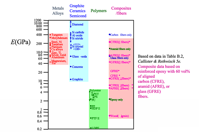
If we look at the figure below it is not surprising that the material listed with the highest E is diamond. Diamond has strong carbon bonds and is incredibly stiff. Larger E indicates a stronger bond. Later when we study composites in more detail, we will see that fibers are added to polymers to increase the stiffness of the material. Increased stiffness implies increased E, which you can see in the figure for the composite/fiber materials.
To Read
Now that you have been introduced to elasticity, please go to your e-textbook and read section 7.3 (pages 71 to 74 in Chapter 4 of Materials for Today's World, Custom Edition for Penn State University) of this lesson's reading. When finished with the reading proceed to the next web page.
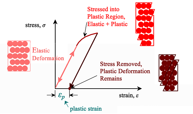
Plastic Deformation
For most metallic materials, the elastic deformation region is relatively small. At some point, the strain is no longer proportional to the applied stress. At this point, bonds with original atom neighbors start to break and reform with a new group of atoms. When this occurs and the stress is relieved, the material will no longer return to its original form, i.e., the deformation is permanent and nonrecoverable. The material has now moved into the region referred to as plastic deformation. In practice, it is difficult to identify the exact point at which a material moves from the elastic region to the plastic region. As shown in the figure below, a parallel line offset by 0.002 strain is drawn. Where that line intercepts the stress-strain curve is identified as the yield strength. The yield strength is equal to the stress at which noticeable plastic deformation has occurred.
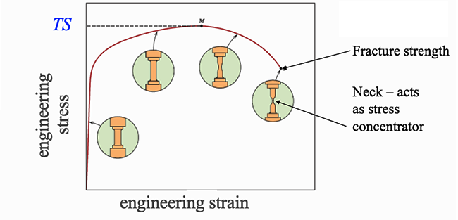
For many materials, the stress-strain curve looks like the curve shown in the figure below. As the stress is increased from zero, the strain increases linearly until it starts to deviate from linear at the yield strength. For increasing stress, the curve proceeds to a maximum, at which point it curves downward toward the fracture point. The maximum corresponds to the tensile strength, which is the maximum stress value for the curve and is indicated by M in the figure. The fracture point is the point at which the material ultimately breaks, indicated by F in the figure.
Resiliency and Toughness
When a person is resilient, we mean that they bounce back from change to their original personality. Resiliency in the material sense is similar. We can define resilience of the material to be the amount of energy the material can absorb and still return to its original state. If we are talking about stressing the material and having it return to its original state, we are talking about the material remaining in the elastic region of the stress-strain curve. It turns out that we can get the energy of elasticity by taking the area under the curve of the stress-strain curve. That area has been highlighted in the figure below, which is the area under the curve from the origin to the yield strength.

Toughness, in contrast to resilience, is how much energy can be absorbed and still keep going. One analogy that can be used when describing toughness is that of a car in a demolition derby. The car is allowed to continue the competition as long as it is capable of moving. It does not matter how many hits and how much destruction has been done to the car, but rather as long as the car can move it can stay in the competition. The toughness of the car is based on how many hits and how much damage the car can sustain and continue in the competition. In the case of materials, the amount of energy that the material can absorb plastically before fracturing is the toughness.
In the figure below, we can see that a material can have a high tensile strength (ceramics) and yet have a small toughness. In addition, materials can be extremely ductile (unreinforced polymers) and also have a small toughness. So, a large toughness (metals) is obtained by having a high tensile strength and a high ductility.

What is a Brittle Material?
Brittle material breaks while little to no energy is absorbed when stressed. The material fractures with no plastic deformation. The material in the figure below marked with (a) shows what a brittle material will look like after pulling on a cylinder of that material. Typically, there will be a large audible snap sound when the brittle material breaks. A brittle material is also known as a material having low ductility. A stress-strain curve for brittle and ductile materials is shown in the figure below. We will talk more about ductile materials in the next section.

You may be asking: why are ceramics so much more brittle than metals? It has to do with the type of bonding. In metals, their metallic bonds allow the atoms to slide past each other easily. In ceramics, due to their ionic bonds, there is a resistance to the sliding. Since in ionic bonding every other atom is of opposite charge when a row of atoms attempts to slide past another row, positive atoms encounter positive atoms and negative atoms encounter negative atoms. This results in a huge electrodynamic repulsion which inhibits rows of ceramic atoms from sliding past other rows. In metals, the sliding of rows of atoms results in slip, which allows the metal to deform plastically instead of fracturing. Since in ceramics the rows cannot slide, the ceramic cannot plastically deform. Instead, it fractures, which makes it a brittle material.
Malleability and Ductility
Malleability and ductility are related. A malleable material is one in which a thin sheet can be easily formed by hammering or rolling. In other words, the material has the ability to deform under compressive stress.

In contrast, ductility is the ability of a solid material to deform under tensile stress. Practically, a ductile material is a material that can easily be stretched into a wire when pulled as shown in the figure below. Recall pulling is applying tensile stress.

If we pull on a rod of material, some of the possible profiles of the rods at fracture are shown in the figure below.
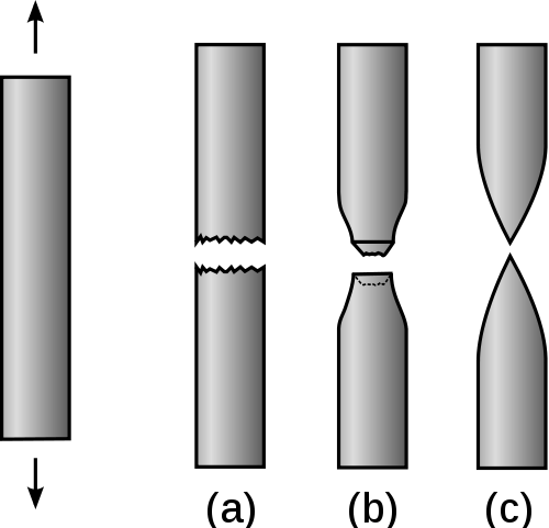
Profile (a) is an example of the material that fractures with no plastic deformation, i.e., it is a brittle material. Profile (b) is an example of a material that fractures after very little plastic deformation. These two profiles would be classified as having low ductility. Profile (c) in contrast is a material that plastically deforms before fracture. This material has high ductility. The stress-strain curves for the brittle, profile (a), and the ductile material, profile (c), are shown in the figure below.

To Read
Now that you have learned a bit about the mechanical behavior of metals, please go to your e-textbook and read pages 75 to 84 in Chapter 4 of Materials for Today's World, Custom Edition for Penn State University to learn more about this subject. When finished with the reading, proceed to the next web page.
Mechanical Behavior of Ceramics
It is difficult to measure the yield strength of ceramics as they tend to fracture before they enter the plastic deformation region, i.e., they are brittle. Examples of two brittle materials that fracture before entering the plastic deformation region are aluminum oxide and glass, as shown in the figure below.

Tensile tests of brittle ceramics are usually not performed. It is difficult to shape these materials into the proper test structure, difficult to grab the brittle material without breaking it, and it is difficult to align the test samples to avoid bending stresses which can destroy the sample. For brittle ceramics, a three-point bending apparatus (shown in the figure below) is used determine the stress-strain behavior, and the measurement results are used to calculate an equivalent modulus of elasticity.

To Read
Now that you have been introduced to the mechanical behavior of ceramics, please go to your e-textbook and read more on this topic on pages 84 to 86 in Chapter 4 of Materials for Today's World, Custom Edition for Penn State University. When finished with the reading proceed to the next web page.
Mechanical Behavior of Polymers
Polymers exhibit a wide range of stress-strain behaviors as shown in the figure below. The brittle polymer (red curve) elastically deforms and fractures before deforming plastically. The blue curve is a plastic polymer and is similar to curves for many metals. Its behavior begins in the linear elastic deformation region. As the curve transitions from the elastic to plastic deformation typically there is a peak stress. For polymer materials, this peak stress is identified as the yield stress. As the material is pulled further, fracture occurs. The stress value when fracture occurs is defined as the tensile strength for polymer materials. The tensile strength can be greater than, equal to, or less than the yield strength. The green curve is a class of polymers known as elastomers. These materials exhibit rubber-like elasticity and will return to their original shape and form unless they are extended to the point of fracture.

While some of the stress-strain curves for polymers might look similar to ones for metals, polymers are mechanically different than metals (or ceramics). A highly elastic polymer may stretch over 10 times the original length before breaking, while a metal might elastically stretch 10% of the original length elastically and may stretch plastically to double the original length before reaching its fracture point. As seen in the figure below, the largest elastic modulus values for polymers are well under the values for ceramics and metals.

As shown in the figure below, the tensile strength of some polymers can rival some ceramics but are no match for even the softest of metals.

To Read
Now that you have learned a bit about the mechanical behavior of plastics, please go to your e-textbook and read pages 87 to 89 in Chapter 4 of Materials for Today's World, Custom Edition for Penn State University to learn more about this subject. When finished with the reading, proceed to the next web page.
Hardness
Hardness is a measure of a material's ability to resist plastic deformation. In other words, it is a measure of how resistant material is to denting or scratching. Diamond, for example, is a very hard material. It is extremely difficult to dent or scratch a diamond. In contrast, it is very easy to scratch or dent most plastics. As shown in the diagram below, hardness increases from the very soft plastics to the incredibly hard diamond with most other materials ranging between.

A common method for measuring the hardness of a material is outlined in the figure below. A very hard-sphere is pushed with a set force into the material. The resulting indent is measured for width and depth. A harder material will have a smaller width and depth, i.e., smaller indentation. Larger hardness results in a high resistance to deformation from compressive loads, i.e., resistance to scratches and dents, and better wear properties.

To Read
Now that you have been introduced to the concept of hardness, please go to your e-textbook and finish the reading for this chapter (pages 90 to 97 in Chapter 4 of Materials for Today's World, Custom Edition for Penn State University). When finished with the reading proceed to the next web page.
Video Assignment: Making Stuff Stronger
Now that you have read the text and thought about the questions I posed, take some time to watch this 53-minute video about trying to find the strongest materials in the world. As you watch this video please pay particular attention to: (1) the ways that materials can be made stronger, (2) how stronger materials can be made lighter, cheaper, or better in other ways, and (3) how new stronger materials are designed for specific applications.
Video Assignment
Go to Lesson 4 in Canvas and watch NOVA's Making Stuff: Stronger Video. You will be quizzed on the content of this video. Skipped for Summer 2024 LEAP.
Summary and Final Tasks
Summary
In this lesson we discussed the stress–strain behaviors of metals, ceramics, and polymers and the related mechanical properties. Understanding and classifying the properties of materials allow us to design, produce, and utilize materials more efficiently and productively. In some cases, understanding materials allow us to utilize them for new applications. Lesson 4 provides us a language to discuss and compare different materials, while the previous lessons on the classification of materials and atomic structure along with upcoming lessons on the structure of materials will inform us regarding how geometric atomic arrangements and atomic structure can affect materials properties. In the next lesson, we will study how metal atoms arrange to form solids and some of the applications of metals.
Reminder - Complete all of the Lesson 4 tasks!
You have reached the end of Lesson 4! Double-check the to-do list on the Overview page to make sure you have completed all of the activities listed there before you begin Lesson 5.
Lesson 5: Structure and Applications of Metals
Overview
The crystal structure of a material can directly affect their properties. For example, gold and silver which share a common crystal structure are much less brittle than the metals beryllium and magnesium which possess a different crystal structure. Also, crystalline and noncrystalline materials of the same composition can possess significantly differing properties. In this lesson, we will discuss how structure can affect materials properties and also introduce imperfections, which can have major impacts on the properties of materials.
Learning Objectives
By the end of this lesson, you should be able to:
- List and explain the contributions to material processing made by the Egyptians.
- Explain the difference between melting and smelting.
- Distinguish between single crystals and polycrystalline materials.
- Describe the difference in atomic/molecular structure between crystalline and non-crystalline materials.
- Draw unit cells for face-centered cubic, body-centered cubic, and hexagonal close-packed crystal structures.
- Define polymorphism and allotropy.
- Sketch the three orthogonal crystal systems (cubic, tetragonal, orthorhombic) and the hexagonal crystal system with proper lattice parameter labels.
- Define isotropy and anisotropy with respect to material properties.
- List and describe the different types of imperfections in a crystal.
Lesson Roadmap
Lesson 5 will take us 1 week to complete. Please refer to Canvas for specific due dates.
| To Read |
Read pp 99-120 (Ch. 5) in Introduction to Materials ebook Webpages on this site for Lesson 5 |
|---|---|
| To Watch | Metal: The Secret Life of Materials |
| To Do | Lesson 5 Quiz |
Questions?
If you have general questions about the course content or structure, please post them to the General Questions and Discussion forum in Canvas. If your question is of a more personal nature, feel free to send a message to the instructor through Canvas email. I will check each of these daily to respond.
Things to Consider...
While you read the material for this lesson in your e-book and on the course website, use the following questions to guide your learning. Also, remember to keep the learning objectives listed on the previous page in mind as you learn.
- What contributions did the Egyptians make in the development of materials processing?
- What is the difference between melting and smelting?
- How do single crystal and polycrystalline material differ in grain structure?
- How do crystal and polycrystalline materials differ in their atomic/molecular structure?
- What is the difference between an amorphous and crystalline material?
- What is the difference between crystal structure and a crystal system?
Copper (Chalcolithic) and Bronze Ages
In the Neolithic Age, which was the period at the end of the Stone Age, the Egyptians were experiencing increasing population along with extensive food production capabilities, several communities in similar stages of development, and an extensive trade network with other civilizations. As the Egyptians entered the Copper and Bronze Ages, their technological advancements in gold, copper, and bronze processing were aided by their access to key natural resources. The figure below from the British Museum shows known natural resources of ancient Egypt.

In the following pages, we will discuss gold, copper, and bronze processing as developed by the Egyptians.
Egyptian Gold Processing
It is not surprising that gold was the first metal processed by the Egyptians. Very few metals are found in their native state, i.e., not bound to other elements in a compound such as a mineral. Copper is very rarely found in nature as an element and iron is typically only found as an element in some meteorites. Iron from meteorites was extremely rare in Egypt and was known as metal from the gods. Gold, however, is routinely found in nature as an element unlike copper and iron, and most other metallic elements. Gold, although rare, can be found as flakes or nuggets. As shown in the illustration below from an ancient Egyptian tomb, the Egyptians used charcoal and blow pipes to reach the temperatures needed to melt gold. Also, ‘slag’ (impurities) were skimmed off the molten gold.

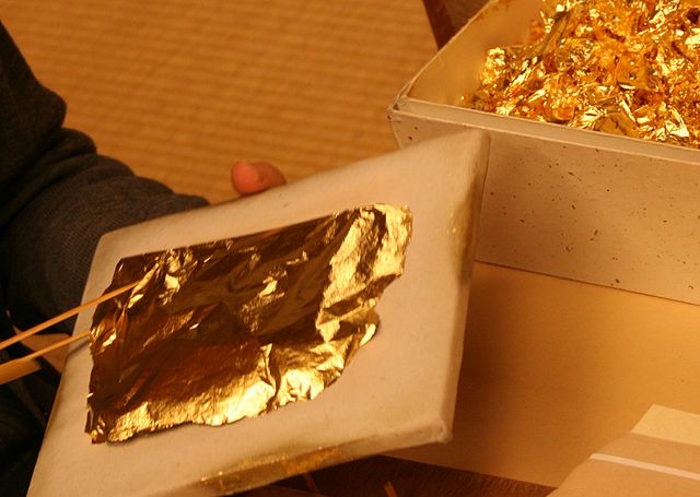
The molten gold was poured into molds to form jewelry and other items. In addition, the Egyptians were able to hammer gold into very thin (5 µm) leafs. Gold is a malleable material. Malleability is a material’s ability to be deformed under compressive stress, i.e., to form a thin sheet by hammering or rolling. A ductile material (ability to be deformed under tensile stress, i.e. can be pulled into a wire) has to be a malleable material as well, but malleable materials do not have to be a ductile material. An example of this is lead. Lead is malleable but when pulled to form a wire it pulls apart. As you can see malleability and ductility are closely related but do not possess the same definition in material science.
The Egyptians believed gold to be a divine material which held magical powers. Electrum is an alloy of gold which is approximately 80% gold mixed with 20% silver. An alloy is a mixture of metals or a mixture of a metal with small amounts of non-metals. We will discuss metal alloys in more detail in the next lesson. In the next section, we will discuss Egyptian copper processing.
Egyptian Copper Processing
Native copper occurs in a very limited supply, so the start of the Copper Age is marked by the discovery of smelting copper from its ores which allows for a ready supply of copper. The two basic naturally occurring copper (II) carbonate minerals are pictured below.


Copper is a very malleable material, unlike flint, which at the beginning of the Copper Age was the dominant weapon and tool material. Although copper is soft it does have a significant advantage over flint. It can be repaired. Native Americans used native copper beginning circa 6000 BCE. As mentioned, the supply of native copper is very limited and its supply was easily exhausted. Copper ores, on the other hand, were readily available. However, to extract the copper from copper ores smelting was required.
What is smelting? Smelting is a process that uses heat and chemistry to drive off other elements such as gases or slag, leaving behind only the metal. Typically, ores are impure and require a flux to separate the metal from the slag. Flux is an additive used to change the impurities from a form that is inseparable from the metal to a form that is separable. For example, adding iron ore as a flux during the smelting of copper can transform the impurity solid silicon dioxide into an iron-silicon oxide. Unlike the solid silicon dioxide which remains in the liquid copper, the iron-silicon oxide floats to the top and can be skimmed off. Smelting is different than melting in that in melting you have to be able to raise the temperature to the melting point of the material. The Egyptians did not have the ability to reach the temperatures needed to melt the copper minerals outright.
How Did Egyptians Discover that Malachite and Azurite Contain Copper?
It is unknown exactly how the Egyptians discovered that malachite and azurite contain copper. Here are a couple of possibilities.
Egyptians used malachite as a pigment and cosmetic, including as a distinctive eyeliner. While a normal open fire would not reach the temperatures required to melt bulk malachite, in powder form it is possible that accidentally putting Malachite powder on the coals of the fire could produce small balls of copper.
A second, and more likely possibility centers around the Egyptians using malachite as a pottery glaze. Small balls of copper could have been formed in the pottery kiln during firing, and then noticed by kiln workers after cooling.
Egyptian Copper Smelting Process

The Egyptian copper smelting process utilized a ’bowl furnace’ which was supplied additional air, to raise the temperature of the fire, through the usage of foot bellows. Malachite and azurite were used as a source ore for the copper, charcoal was used as the reducing agent to separate oxygen from the copper, and iron ore was used as the ‘flux’ to bind and float away impurities. The advantage that copper has over bone, wood, or flint, as a tool or weapon, is that when damaged it can be repaired. However, like most pure metals, i.e., metals with a low level of impurities, copper is soft. It turns out that intentionally or unintentionally adding another soft metal in small amounts can make the host material stronger and harder. This is a process known as alloying, which we will be discussing further in the next lesson.
Now let’s go to the next section and look at the soft metal, tin, that the Egyptians added to copper to produce a more durable and harder metal.
Egyptian Smelting of Tin

It is not known how exactly the Egyptians discovered the smelting of tin. In some ways, it is a bit surprising. Cassiterite, SnO2, the mineral used as the ore for extracting tin, is extremely difficult to find and not particularly noteworthy, i.e., it does not stand out in the field. It is hard and, like gold, has a high specific gravity. Having a high specific gravity means that flakes or nuggets of cassiterite, like gold, would settle to the bottom of a slurry if panning for gold. So, while it is difficult to find sources of cassiterite it might have been possible to backtrack upstream by finding cassiterite flakes downstream of sources.
While it might be counterintuitive to think that the Egyptians added an even softer metal, tin, to copper to make it harder, it is possible that the Egyptians thought that whatever made cassiterite hard would be transferred to the copper. The smelting of tin is very similar to the smelting of copper. Charcoal is also used as the reducing agent. Tin, unlike copper, is too soft for practical purposes. However, when it’s mixed with copper in small amounts, typically 5 – 10% tin, it can produce a much harder metal than unalloyed copper or tin. Please proceed to the next section to learn more about this new harder metal, bronze.
Egyptian Bronze Processing

Bronze is an alloy of copper and tin. Tin is a slightly bigger atom than copper. In bronze, typically 5 – 10% is tin and the rest is copper. The slightly larger tin atoms replace copper atoms in the copper crystalline structure as shown in the figure below. We will learn more about metal alloys in this lesson and the next. Although copper and tin are both soft metals and not ideal for tools or weapons, the combination that produces bronze is much harder than copper or tin. As we will learn later, this is due to the larger tin atoms making it harder for rows of copper atoms to move. This results in bronze being harder.

In the practice of producing bronze, the Egyptians placed tin with copper ingots into clay crucibles. The clay crucibles were lowered into a charcoal fire which could exceed 1100 °C through the use of blowing air using foot bellows. The Egyptians would then stir, remove the slag, and pour the melt into a mold.
Why Did it Take So Long Between the Bronze Age and the Iron Age?
The beginning of the Bronze Age occurred around 3500 BCE and the beginning of the Iron Age began around 1000 BCE. Why did it take 2000 years for bronze to be replaced by iron? Looking around us we see structural steel and concrete seemingly everywhere in our modern cities. However, the processing of iron is not a trivial process.
Due to limitations in furnace designs, i.e., the maximum obtainable temperatures, the availability and quality of iron varied greatly. As we’ll see in the next lesson’s video, Secrets of the Viking Sword, throughout history there have been legendary quality swords, i.e., Damascus and Samurai to name just a couple. These swords were produced using time-intensive and, many times, ritualistic processes. These blades were produced in areas known in the modern day as Iran, Japan, and China. Most of the iron used in weapons during the Iron Age, i.e., Roman swords, was a low-density iron sponge-like material. This sponge-like iron was then pounded to shape, densify, and remove impurities. Bronze was superior to the iron produced commonly, so why did iron ultimately replace bronze?
Bronze weapons were indeed of higher quality than the common iron weapons typically produced. However, tin, which is required for the production of bronze, is not abundantly available. As a consequence, bronze weapons were the weapons utilized by nobles, royalty, pharaohs, etc. The common foot soldier was not going to possess bronze weapons; there were not enough to go around.
Unlike tin, iron ore is readily available. So, although inferior to bronze, an army of hundreds or thousands could be equipped with iron weapons, which was not practical with bronze weapons. So, the ability to produce large numbers of iron weapons overcame the advantages of bronze. Eventually, time and further development allowed for the production of these so-called legendary swords which supplanted bronze as the weapon material of choice for the nobility. But it wasn’t until much later, during the advent of the Industrial Revolution, that advancements in furnace design and process control enabled the reliable and massive production of the iron alloy known as steel. In this lesson’s video, the importance of steel and how the production of steel was changed during the beginning of the Industrial Revolution will be showcased. We will return to this topic at the beginning of the next lesson on metal alloys.
Now, let’s take a step back from our discussion on the historical development of metal processing and begin an introduction to the structure of metals.
Structure and Application of Metals
When you mention crystal to most people, they think of fine glassware. Metal is not the first thing that comes to mind. But, in fact, most metals are crystalline, and it is rather difficult to make noncrystalline metals. Crystalline materials have their atoms arranged in a periodic, ordered 3D array. Typically, all of the metals, many ceramics, and some polymers are crystalline. Noncrystalline materials have atoms with no periodic arrangement, i.e., a random order. Noncrystalline material can result when you have complex structures or you rapidly cool from the liquid state to the solid state. Amorphous material is another name for noncrystalline material.
Why do metals form crystals? It turns out that the lowest energy for metal atoms occurs when the atoms are packed together as tightly as possible. If you’ve ever tried to put many small pieces into a large box, you know that if you put the pieces in the box in an ordered fashion you can fit much more in the box than if you just throw things into the box in a disorderly fashion. So, for metals, ordered structures tend to be nearer the minimum energy and are more stable. In addition, since metallic bonds are nondirectional it is much simpler for metal atoms to densely pack than it is for ceramics and polymers. So how do metal atoms pack together? In the next section, we will look at one of the ways that metal atoms pack together.
Simple Cubic Crystal Structure
Start by taking four atoms and arranging them in a square. Then take four more atoms and arrange them in a square. Then put the first square on the second square to form a cube with eight atoms, one at each corner. This structure is the simple cubic crystal structure. It turns out that only the metal Polonium (Po) has this crystal structure. The reason this crystal structure is so rare is that packing atoms in this way does not lead to a very high packing density. In the next section, we will add one atom to the simple crystal structure and produce a crystal structure that is much more common.

Body Centered Cubic Structure (BCC)
Let's take our simple cubic crystal structure of eight atoms from the last section and insert another atom in the center of the cube. This new structure, shown in the figure below, is referred to as body-centered cubic since it has an atom centered in the body of the cube. Some examples of metals that possess this crystalline structure include the α phase of iron, chromium, tungsten, tantalum, and molybdenum.

Face Centered Cubic Structure (FCC)
If, instead of starting with a square, we start with a triangle and continue to add atoms, packing as tightly as we can, we will end up with a layer of atoms as shown in the figure below.

Now let me put an atom on top of that first layer over one of the 'B' positions and let it rest down into one of the valleys. I can now place two more atoms in nearby 'B' positions so that each will rest in their own valley in such a way that all three atoms will touch and form a triangle. Now let me add more atoms to the second layer, packing them in as tightly as possible. These two layers are shown in the figure below. If you look closely, you should be able to see that the second layer only covers half of the valleys produced by the first layer. The 'C' valleys are left uncovered. In fact, half of the valleys of the second layer lineup with the unoccupied 'C' valleys of the first layer.

Now let’s put a third layer where the atoms are placed where the unoccupied valleys of the first two layers lineup, the 'C' valleys. It is a little difficult to visualize, but if one of the top layer atoms is one corner of our cube and that corner is pointing out then we obtain the cube shown in the figure below.

This crystal structure is known as face-centered cubic and has atoms at each corner of the cube and six atoms at each face of the cube. It is shown in the figure below. This structure, as well as the next structure we are going to discuss, has the atoms packed as tightly as theoretically possible. Metals that possess face-centered cubic structure include copper, aluminum, silver, and gold.

In the next section, we will discuss our fourth and last crystal structure.
Hexagonal Close Packed Crystal Structure (HCP)
If you look at the figure below, you might think that hexagon close-packed crystal structure is more complicated than face-centered cubic crystal structure. In fact, it is a simpler structure.
Think back to the last section where we constructed first one layer of atoms and then a second layer of atoms for face-centered cubic structure. Now, for hexagonal close-packed crystal structure, we do not construct a third layer. Instead, the third layer is simply the first layer repeated, the fourth layer is the second layer repeated, and so on and so on as shown in the figure below.

It turns out that face-centered cubic and hexagonal close-packed crystal structures pack atoms equally tightly. Some metals with hexagonal close-packed crystal structures include cobalt, cadmium, zinc, and the α phase of titanium. A more typical representation of the hexagonal close-packed structure is shown in the figure below. In this representation a hexagon on the top and on the bottom sandwich a triangle in between the two hexagons.

Please proceed to your e-textbook and read the first chapter of this lesson’s assigned reading. Please return back to this website after completing that reading.
Reading Assignment 1
Now please proceed to the first reading assignment (shown below) from your e-book. After you have completed that reading please return to this page and continue the web reading.
Reading Assignment
Read pp 99-120 (Ch. 5) in Introduction to Materials ebook
Now you should be able to distinguish between single-crystal and polycrystalline materials. If you cannot draw unit cells for face-centered cubic, body-centered cubic, and hexagonal close-packed crystal structures, you should review those.
Metals routinely form crystals. However, sometimes metal is formed from many grains rather than a single crystal. A grain is a region of single crystallinity and material with many grains is a material with many crystals (grains) that are misaligned to each other. This would be termed a polycrystalline material.
Many materials, e.g. iron, titanium, and carbon, possess two or more distinct crystal structures, which is referred to as allotropy or polymorphism. We have discussed metals as though they form perfect crystals, but it turns out that in real life a perfect crystal is not possible.
In the next section, we will introduce crystal imperfections, which in many cases lead to desirable materials properties.
Imperfections in Solids
There is no such thing as a perfect crystal. Crystalline imperfections (or defects) are always present. In addition, impurity atoms are always present. Many of the properties of materials are sensitive to the presence of imperfections, and not necessarily in an adverse way.
So, what kind of imperfections exist in solids? One way to classify imperfections is by their dimensionality. Point defects exist by definition as a point (0 – dimensional) and include vacancies, interstitial atoms, and substitutional impurity atoms. These point defects are shown in the two figures below and will be discussed further in the reading.


One-dimensional or linear defects are called dislocations. An edge dislocation is when a half plane of atoms disrupts the overall crystal structure. A screw dislocation is when a half twist disrupts the overall crystal structure. A mixed dislocation is a dislocation that combines both an edge and screw dislocation together.
Grain boundaries are regions between different grains within a material. They are classified as an interfacial defect and are two-dimensional.
Now proceed to the second chapter of the Lesson 5 reading assignment and complete the reading.
Reading Assignment 2
As you do the following reading, here are some questions to keep in mind.
- Is there really a 'pure' metal?
- What are point defects?
- What are edge dislocations?
- What are screw dislocations?
- Can you name a two-dimensional imperfection in a crystal?
Reading Assignment
Read pp 121-135 (Ch. 6) in Introduction to Materials ebook
Video Assignment: Metal: The Secret Life of Material
Now that you have read the text and thought about the questions I posed, go to Lesson 5 in Canvas and watch "Metal: The Secret Life of Materials" (51 minutes) about how science has unraveled the secrets of metal at the atomic level. In "Metal: The Secret Life of Materials," materials scientist Dr. Mark Miodownik explains the history, production, and uses of metals. Metals can be strong enough to build modern cities but soft enough to be crumbled in hand.
Video Assignment
Go to Lesson 5 in Canvas and watch the Metal: The Secret Life of Material video. You will be quizzed on the content of this video.
Summary and Final Tasks
Summary
Lesson 3 was concerned primarily with the various types of atomic bonding and how bonding is determined by the electron structures of the individual atoms. In this lesson, the structure of materials was discussed beginning with how metal atoms arrange to form solids. Within this framework, concepts of single crystal (highly ordered), polycrystalline (many unaligned regions of crystalline material), and non-crystalline (little to no order, also known as amorphous) materials were introduced. For crystalline solids, the notion of crystal structure was presented, and specified in terms of a unit cell.
Reminder - Complete all of the Lesson 5 tasks!
You have reached the end of Lesson 5! Double-check the to-do list on the Overview page to make sure you have completed all of the activities listed there before you begin Lesson 6.
Lesson 6: Types and Applications of Metal Alloys
Overview
In this lesson, we will discuss the wide range of commercial applications of ferrous alloys, which includes steel. However, ferrous alloys do have some limitations including having low electrical conductivity compared to other metals, being heavy, and corroding in typical application environments. In addition to the ferrous alloys in this lesson we will look at a range of other (non-ferrous) metal and alloy systems: copper, aluminum, magnesium, and titanium alloys; the refractory metals; the superalloys; the noble metals; and miscellaneous alloys, including those that have lead, tin, zirconium, and zinc as base metals. Many of these non-ferrous metals and alloys have advantages over the ferrous alloys for particular applications.
Learning Objectives
By the end of this lesson, you should be able to:
- Name four different types of steels and cite compositional differences, distinctive properties, and typical uses for each.
- State different types of nonferrous alloys.
- List current and historical applications of nonferrous alloys.
- Cite distinctive physical and mechanical characteristics of nonferrous alloys.
Lesson Roadmap
Lesson 6 will take us one week to complete. Please refer to Canvas for specific due dates.
| To Read | Read pp 136-179 (Ch. 7 & 8) in Introduction to Materials ebook |
|---|---|
| To Watch | The Secrets of the Viking Sword |
| To Do | Lesson 6 Quiz |
Questions?
If you have general questions about the course content or structure, please post them to the General Questions and Discussion forum in Canvas. If your question is of a more personal nature, feel free to send a message to all faculty and TAs through Canvas email. We will check daily to respond.
Types of Metal Alloys
In this lesson, we are going to take a closer look at metal alloys. First, we will define what an alloy is and how dislocations strengthen alloys. The e-textbook breaks metal alloys into two classes of metal alloys: ferrous and nonferrous alloys. Ferrous is simply the Latin name for iron, so ferrous alloys are simply iron alloys (which means that it is mostly iron mixed with lesser amounts of other metals or nonmetals) and nonferrous alloys are non-iron alloys. In the reading for this lesson, you will see the composition, properties, and applications of a wide variety of metal alloys. The video for this lesson highlights the properties and applications of some of the metal alloys and puts the materials development of the highlighted metal alloys in historical context.
What Are Metal Alloys?
An alloy is a mixture of a metal with another element, either metal or nonmetal. If we start with a base metal and we add impurity atoms there are two possible outcomes if the two mix. The two different cases are highlighted in the figure below. In the substitutional solid case, the impurity atoms replace the host atoms in the lattice. In the interstitial situation, impurity atoms squeeze between the host atoms.
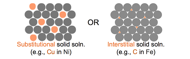
In addition to mixing, it is possible for regions of a new phase to form. An illustration of the formation of a second phase in a solid solution is shown below. The second phase can have a different composition and often a different structure.

To Watch
Now watch the following video (4:44) on alloys and how dislocations harden alloys:
After watching the video, please proceed to the next section on the development of iron smelting.
Why Did it Take So Long?
Why did it take so long (~2,000 years) for humankind to apply the concepts of smelting copper and bronze to the development of iron? And then another 3000 years to develop steel?
The major issue with the smelting of iron is that with the technology used for smelting of copper and bronze the temperature that is obtainable results in solid iron. So rather than having molten iron, the smelting of iron results in a sponge-like solid mass of impure iron.
As we will see later in the video, impurities could be pounded out of iron by hitting it. So, until the Industrial Revolution, iron could only be produced as a wrought alloy. A wrought alloy is amenable to being mechanically deformed, i.e., pounding it into a desirable shape. Since iron could not be melted it could not be cast in the molds. There were also limits to controlling impurities.
In England in 1709, Abraham Darby started to use coke instead of charcoal as his fuel source to smelt iron ore. Coke, a form of coal, allowed him to build larger and more efficient furnaces than charcoal could support. These furnaces allowed Darby to reach higher temperatures. The temperatures reached were still not high enough to melt pure iron. However, iron that has around 4.3 weight percentage of carbon has a much lower melting temperature than pure iron. Although not pure iron, the iron that he could cast (since it was molten) allowed him to manufacture cast iron pots that could compete successfully with brass.
In the 1850s, Henry Bessemer proposed an incredibly bold idea. Bessemer began using very large blast furnaces (shown below), which could produce 3 to 4 tons of molten iron in a single run. Oxygen was blasted through the furnace, which resulted in higher temperatures and the oxygen combining with carbon to form CO2 gas, which bubbled out of the iron. Initially, Bessemer’s process was not reliable. There were issues with phosphorus and sulfur contamination as well as difficulty producing iron with desired target carbon content. This latter issue was resolved by removing all carbon during the process and adding in desired amounts of carbon after purification of the iron.

Now, proceed to the reading and video assignment for this lesson. We will then explore in more detail aluminum alloy and, one of my favorite alloys, metallic glass.
Reading Assignment
Things to consider...
When you read this chapter, use the following questions to guide your reading. Remember to keep the learning objectives listed on the overview page in mind as you learn from this text.
- Often a materials problem is really one of selecting the material that has the right combination of characteristics for a specific application. Do all the ferrous alloys have the same materials properties? What are some of the differences?
- What are the different types of nonferrous alloys?
- How have nonferrous alloys been used in the past?
- How are the nonferrous alloys being used currently?
- What are the distinctive physical and mechanical characteristics of the different nonferrous alloys?
- What are the five types of cast iron?
- How do the microstructure and mechanical characteristics of the five types of cast iron compare?
Reading Assignment
Read pp 136-179 (Ch. 7 & 8) in Introduction to Materials ebook
Video Assignment: Secrets of the Viking Sword
Now that you have read the text and thought about the questions I posed, take some time to watch this 53-minute NOVA video about using cutting edge science, old-fashion detective work, and modern craftsmanship to reconstruct a legendary Ulfberht Viking sword. As you watch this video see if you can apply what you know about carbon content in ferrous alloys to the properties of the sword being manufactured in this video.
Video Assignment
Go to Lesson 6 in Canvas and watch the Secrets of the Viking Sword video. You will be quizzed on the content of this video. Skipped for Summer 2024 LEAP.
Aluminum Alloy

Aluminum and its alloys were introduced in your e-textbook. The history of the development and applications of aluminum and its alloys were covered in the video for this lesson. Now I am going to expand on this material and highlight the role of aluminum in airplane development.
Aluminum is the third most abundant element in the Earth's crust, after oxygen and silicon, and is the Earth's most abundant metal. It is about 8% of the crust by mass, but it is rarely found as a native metal as it is very chemically active. Its oxide forms more readily than the oxide of iron and, unlike the oxide of iron, once formed it blocks oxygen and water from penetrating the aluminum oxide. This results in aluminum being very corrosion-resistant. Iron, on the other hand, forms rust which does not block oxygen and water, so iron pieces will rust to completion if left long enough in a wet atmospheric environment. Aluminum has a low density, which makes it a candidate for lightweight applications.
Aluminum Electrolysis
Although aluminum is abundant in nature, it occurs chemically bound to other elements, and there is no known way to smelt aluminum using traditional smelting methods. Because of this limitation, before the 19th century, pure aluminum was rarer than gold. In the 19th century, people learned how to use electrolysis to extract aluminum from aluminum oxide, AlO2. As you can see from the figure below aluminum production has continued to increase ever since.

Typically, aluminum oxide is extracted from the mineral bauxite, and then aluminum is further processed from the aluminum oxide. Visit this website to access the list of where aluminum oxide is produced [28]. Although aluminum oxide is used as an abrasive material most of the aluminum oxide is used for the production of aluminum. For more on the electrolysis process for the extraction of aluminum from aluminum oxide, please watch the fuseschool.org video linked below.
Watch Now
Please watch the following short video (3:13), How to Extract Aluminum Using Electrolysis, on the extraction of aluminum using electrolysis before proceeding to the next section on building lighter aircraft.
Building a Lighter Aircraft

The lighter that we can build safe aircraft the better. Reducing the operating empty weight of commercial aircraft can allow for an increase in the passengers, baggage, and cargo that the plane can safely transport. Early aircraft were made of wood and fabric. An example of an early aircraft is shown in the figure below. This provided a good combination of lightness and strength but required reinforcing struts, which added weight and drag and resulted in multiple wing designs.

Improved airplane engine designs resulted in more powerful engines and higher airspeeds. As speed increases, drag increases nonlinearly. Single wing (less drag) airplane designs were required to take advantage of the improvements in speed.
All Metal Monoplanes
The first all metal monoplanes were developed during World War I. These were faster, but it was quickly realized that they did not climb well. Although more powerful than the initial airplane engines, the engines of World War I did not have enough power to lift the all-metal monoplanes quickly enough.

Wood, iron, and aluminum are possible materials for making aircraft wings. How do the densities of these materials compare? The density of water is 1 g/cm3 by definition at standard temperature and pressure. Wood floats in water so its density must be less than 1 g/cm3. Its density ranges from 0.45 to 0.85 g/cm3. Iron and aluminum do not float, so their densities must be greater than 1 g/cm3. Iron's density is equal to 7.9 g/cm3 and aluminum's density is equal to 2.7 g/cm3. So, in theory, it should be possible to reduce the weight of an airplane by utilizing aluminum instead of iron. Aluminum is about 1/3 the density of iron. But there is a problem: aluminum is not strong and alloying does not strengthen the material the way it does in bronze and iron. Aluminum needed to be strengthened, but how?
Hardened Aluminum Alloys
In 1901, German metallurgist Alfred Wilm was working to harden aluminum-copper alloys. The work was not going well so in frustration he went on holiday (vacation). Upon his return, he found a harder material and after many years of work developed a commercially viable age-hardened aluminum alloy. Age-hardened aluminum, which is about three times lighter than iron, replaced iron in aircraft manufacturing. A photo of an early aluminum-bodied aircraft is shown below.

Age hardened aluminum is not as strong as iron so additional aluminum is needed which does offset some of the weight savings. The video in our later Synthesis, Fabrication, and Processing of Materials lesson has more on the use of aluminum in the construction of a modern commercial jet airliner. In the photo below is a Boeing 787 Dreamliner which utilizes a composite airframe, not aluminum. Boeing claims that this airliner is 20% more fuel-efficient than previous generations of airliners.

Now please proceed to the next section on one of my favorite alloys, a future star, a non-crystalline metal.
Metallic Glass
Most metals are crystalline. In fact, it is typically very difficult to make a noncrystalline metal. The following short video highlights metals that are noncrystalline, i.e., amorphous. These materials are sometimes referred to as metallic glasses.
To Watch
After viewing this video please proceed to the summary page of this lesson.
Summary and Final Tasks
Summary
The extremely versatile range of different metals and alloys have produced an incredible range of application for these metals and alloys. In this lesson, we have explored how ferrous metals and the many different non-ferrous metals and alloy systems are historically and currently used. Understanding the strengths and weaknesses of these materials can allow one to properly select the right material for the desired application and the environment in which the application exists. In the next lesson, we will be looking at ceramics and their role as one of the primary materials.
Reminder - Complete all of the Lesson 6 tasks!
You have reached the end of Lesson 6! Double-check the to-do list on the Overview page to make sure you have completed all of the activities listed there before you begin Lesson 7.
Lesson 7: Structure and Applications of Ceramics
Overview
As we continue to explore how the crystal structure of a material can directly affect their properties, we will turn our attention to ceramics. As an example of the role of crystal structure, noncrystalline ceramics and polymers normally are optically transparent; the same materials in crystalline (or semicrystalline) form tend to be opaque or, at best, translucent. In this lesson, we will continue our discussion of how structure can affect materials properties and look at some materials applications of ceramic materials.
Learning Objectives
By the end of this lesson, you should be able to:
- Discuss the early development of ceramics.
- Identify unit cells for sodium chloride, cesium chloride, zinc blende, diamond cubic, fluorite, and perovskite crystal structures.
- Define cation and anion.
- Name three forms of carbon and note at least two distinctive characteristics for each.
- Describe the process that is used to produce glass-ceramics, characteristics, and list several commercial applications.
- Name the two types of clay products and give examples of each.
- Cite important requirements that commonly must be met by refractory ceramics and abrasive ceramics.
Lesson Roadmap
Lesson 7 will take us 1 week to complete. Please refer to Canvas for specific due dates.
| To Read | Read pp 180-214 (Ch. 9 & 10) in Introduction to Materials ebook |
|---|---|
| To Watch | Ceramics: The Secret Life of Materials |
| To Do | Lesson 7 Quiz |
Questions?
If you have general questions about the course content or structure, please post them to the General Questions and Discussion forum in Canvas. If your question is of a more personal nature, feel free to send a message to the instructor through Canvas email. Email, discussion boards, internal Canvas messages are checked daily.
First Known Ceramics
The first known clay figurines date from 29,000 to 25,000 BCE. The clay figurines were found in what is now the Czech Republic and originally were fired at low temperatures. One of the figurines is shown below. Clay is composed of ceramic plates which are separated by water. In this wet form, clay is very plastic and can be molded. The water allows the plates to move past each other. When clay is dried or fired, water is driven off and, when fired, heat enables atomic bonding which locks the plates together. Done properly, the fired clay becomes hard, non-plastic, and brittle.

Around 14,000 BCE, tiles were being made in Mesopotamia (modern day Iran) and India, with pottery making beginning around 10,000 – 9,000 BCE. Around 10,000 BCE the roping or coiling method of pottery making was being used to make pots in Japan (see figure below). Recall that this technique was described in the video Secrets of the Terracotta Warriors as the method used by the Chinese to produce the terracotta warriors.

In the next section, we will look at one of the precursor steps to glass containers, Egyptian faience.
Egyptian Faience
Developed around 4,000 BCE, Egyptian faience is a glaze, or a coating used to color, decorate or waterproof an item, which is typically fused to a ceramic body through firing. Before the discovery of a process to produce glass, Egyptians used glazing to produce containers (see figures below). They combined silica (SiO2), lime (CaO), and soda (Na2O) to form their glaze. During drying, the lime, soda, and impurities move to the surface. When fired above 800 °C a glassy crust forms which ‘cements’ the piece together. The impurities provide color, while the lime protects the piece from the atmosphere. In addition, the lime, when combined with silica, lowers the melting point of silica so that firing at above 800 °C allows the glassy crust to form.


It took about 2,500 years to move from glazing to completely glass containers, which seems like a really long time when you consider that the primary raw material for glass, silica, is very readily available. It is just sand. In the next section, we will take a look at why it took so long for humankind to begin producing glass.
Silica (SiO2)
Silica (structure shown in the top figure below) has a melting temperature of 1700 °C. This is considerably higher than temperatures that are possible with charcoal and a blow pipe (800 - 1200 °C). But adding sodium changes things drastically. Sodium bonds to only one Si atom, so it breaks the ordered network of silica (see lower figure below). This results in a shortening of bond lengths which reduces the melting temperature to around 1000 °C, which is possible to reach with charcoal and a blow pipe. The effect of adding sodium to silica to lower the melting temperature appears to have been discovered around 1,500 BCE.


In the 1st century BCE, the Romans developed glass blowing (which has remained relatively unchanged since that time) and the production of glass products increased. Glass is easier to produce than glazing products. An interesting side note is that the Romans recycled glass. In the next section, we'll discuss the bonding of ceramics and compare it to metallic bonding.
Ceramic Bonding
Recall that the predominant bonding for ceramic materials is ionic bonding. In ionic bonding, a metal atom donates electrons and a nonmetal atom accepts electrons. This electron transfer creates positive metal ions (cations) and negative nonmetal ions (anions), which are attracted to each other through coulombic attraction. The nature of ionic bonding (creation of cations and anions) results in several differences between ionic and metallic bonding. First, ionic bonds in solids are quite directional, i.e., there are certain preferred angles. Second, to maintain charge balance the cations and anions have to be in certain ratios. Thirdly, it turns out, to form stable structures it is necessary to maximize the number of oppositely charged ion neighbors (as shown in the figure below). All of these factors make ceramic structure inherently more complex than metal structures and, as we will discuss later, also make ceramics brittle.

Now, please proceed to the reading for this lesson (shown on the next page).
Reading Assignment
Things to consider...
When you read these chapters, use the following questions to guide your reading. Remember to keep the learning objectives listed on the overview page in mind as you learn from this text.
- What are the common unit cells for ceramic materials?
- What is a cation and an anion?
- Carbon can exist in many forms, what are they and how do the structure and properties differ between the different forms?
- Historically, glass-ceramics have been very important, what processes have been used throughout history and what commercial applications have been produced?
- Clays are another important class of historical materials, what are some of the clay products?
- What are refractory and abrasive ceramics, and what are some important requirements that must be met for their use?
Reading Assignment
Read pp 180-214 (Ch. 9 & 10) in Introduction to Materials ebook
Why is Glass Transparent?
Glass is one of the noncrystalline (amorphous) forms of quartz (SiO2). Quartz is crystalline SiO2 (structure shown in figure (a) below), while fused silica is SiO2 which is amorphous SiO2 without impurities ( the structure is shown in figure (b) below).

In practice, impurities (such as sodium shown in the figure below) are added to the glass to lower the melting temperature and the viscosity of the glass to make it easier to work the glass at lower temperatures.
Glass's amorphous structure breaks up the band structure of SiO2 such that there are no electronic states that electrons can jump to by absorbing visible light in glass. Here is a TED-Ed video by Mark Miodownik (the host of the Secret Life of Materials videos) to explain this in more detail. In the next sections, we are going to discuss why glass is brittle and how glass is being engineered not to be so brittle.
Watch Now
The Glass Age
Let’s take a look at this introduction to the Glass Age. This video was produced by glass manufacturer Corning Incorporated and is hosted by Myth Busters Adam Savage and Jamie Hyneman.
To Watch
In the next section, we will discuss why ceramics are brittle and metals are not.
So Why are Ceramics Brittle?
Why can metals be scratched and develop cracks and yet not catastrophically fail? The reason is that metals can slide along slip planes to break the crack up. Take a look at the following video showing schematically how a crack in a metal becomes a blunted crack and a void, which can effectively stop the initial crack from growing and catastrophically failing (fracture). This is in contrast with the case of ceramics (in this case, glass). As we have mentioned before in this class, the atoms cannot easily slide past one another. This is due to the fact that in a ceramic we have predominately ionic bonding, which results in positive and negative ions alternating. So, if a row of atoms attempts to slide past the next row of atoms this would move positive ions towards positive ions and negative ions towards negative ions. That is typically too costly from a free energy point of view. Instead of stress caused by the crack being relieved by slipping, the crack keeps growing, usually to fracture, as shown in the following (1:13) animation.
To Watch
So, can anything be done to prevent cracks in ceramics from growing out of control? One method is to put the surface of the glass under compressive stress (we will discuss this further in the next section). When you do this, you are building in a stress to help you with a property of the glass. This is different from annealing glass. In the case of annealed glass, the glass is heated, but not melted, and residual stress is allowed to release.
Compressive Surface Stress
When the surface of glass is under compressive stress and cracks develop on the surface, the stress acts to close the cracks and thus prevent them from growing to the point of fracture. The following video, produced by glass manufacturer Corning Incorporated and hosted by Myth Busters Adam Savage and Jamie Hyneman, discusses one commercial product called Gorilla Glass that utilizes compressive surface stress to make glass much more fracture resistant and flexible.
To Watch
You have now completed the reading for this lesson, please proceed to the next page which will introduce the video for this lesson.
Video Assignment: Ceramics: The Secret Life of Material
Now that you have read the text and thought about the questions I posed, go to Lesson 7 in Canvas and watch "Ceramics: The Secret Life of Materials" (51 minutes) about the story of how clay, concrete, and sand (ceramics) have been used to build our 21st-century cities. In "Ceramics: The Secret Life of Materials," materials scientist Dr. Mark Miodownik explains how materials from the Earth have been transformed into the building materials and technology of our modern lives.
Video Assignment
Go to Lesson 7 in Canvas and watch the Ceramics: The Secret Life of Material video. You will be quizzed on the content of this video.
Summary and Final Tasks
Summary
In this lesson, we continued to explore how the crystal structure can affect materials properties, in this case, the properties of ceramic materials. In addition to learning about ceramic crystal structure, the properties of the several forms of carbon were presented. These property combinations make carbon extremely important in many commercial sectors, including the cutting-edge field of nanotechnology that we will explore further in a later lesson. Numerous applications of ceramics, including glass, clays, refractories, and abrasives were introduced and discussed.
Reminder - Complete all of the Lesson 7 tasks!
You have reached the end of Lesson 7! Double-check the to-do list on the Overview page to make sure you have completed all of the activities listed there before you begin Lesson 8.
Lesson 8: Structure and Applications of Polymers
Overview
Although natural polymers have been used by mankind for many centuries, the use of polymers has exploded with the development of synthetic polymers within the last 100 years. Due to satisfactory properties, ease of production, and lower costs, synthetic polymers have replaced many metal, wood, rubber, and fiber parts in many materials applications. In this lesson, we look at the molecular structures of polymers and the development of numerous polymers that are synthesized from small organic molecules. Several different types of end uses of polymers in materials applications including plastics, fibers, coatings, adhesives, films, foams, and advanced materials will be discussed.
Learning Objectives
By the end of this lesson, you should be able to:
- Describe a typical polymer molecule in terms of its chain structure and, in addition, how the molecule may be generated from repeat units.
- Cite the differences in behavior and molecular structure for thermoplastic and thermosetting polymers.
- Draw repeat units for polyethylene, poly(vinyl chloride), polytetrafluoroethylene, polypropylene, and polystyrene.
- Name and briefly describe the four general types of polymer molecular structures.
- Name and briefly describe the four types of copolymers.
- Define hydrocarbon, unsaturated hydrocarbon, saturated hydrocarbon, and isomerism.
- Cite the seven different polymer application types and note the general characteristics of each type.
Lesson Roadmap
Lesson 8 will take us 1 week to complete. Please refer to Canvas for specific due dates.
| To Read |
Read pp 215-231 (Ch. 11) in Introduction to Materials ebook Read pp 232-245 (Ch. 12) in Introduction to Materials ebook |
|---|---|
| To Watch | Plastic: The Secret Life of Materials |
| To Do | Lesson 8 Quiz |
Questions?
If you have general questions about the course content or structure, please post them to the General Questions and Discussion forum in Canvas. If your question is of a more personal nature, feel free to send a message to the instructor through Canvas email. The instructor will check daily to respond.
What is a Polymer?
In this lesson, we will introduce the structure, history of development, and properties of polymers. The roots of the word polymer are actually very descriptive of a polymer. The root ‘mer’ means unit, and poly means many. Taken together, the word polymer can be deconstructed as many units. Typically, ‘mer’ is referred to as a monomer. ‘Mono’, which is the root for one, literally translates as one 'mer'. A commonly used definition of polymer is a material that is composed of many monomers (from 10s to 1000s) all linked together to form chains. A monomer can be composed of one to many atoms which form the base unit which is repeated to form a polymer, as represented in the figure below.

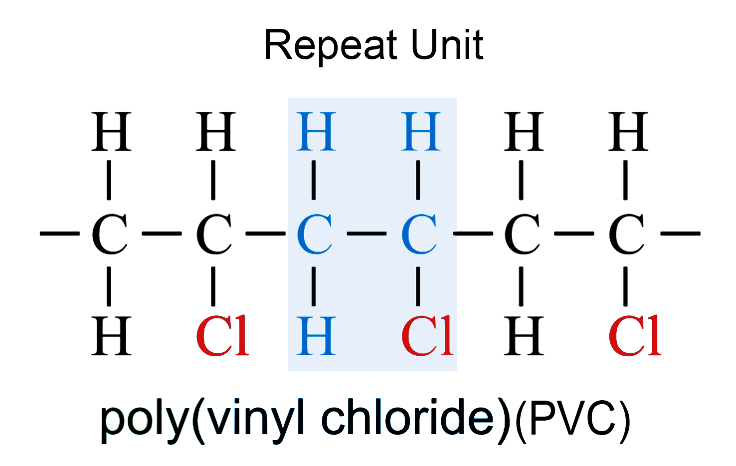
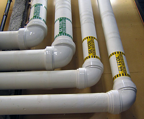
We will also study how chains of polymers are constructed. Polymers can resemble spaghetti noodles (linear), ladders (cross-linked), long chains with smaller chains hanging off the main chain (backbone) known as branched polymers, elaborately complex structures (network), or a mixture of some or all of these basic types. Other polymers, known as copolymers, are constructed from two distinctly different starting monomers and are classified as random, alternating, block, or graft polymers.
Now, watch this TED-Ed video titled, “From DNA to Silly Putty, the Diverse World of Polymers” (4:59), before proceeding on to the next section of our lesson.
To Watch
Natural Polymers
DNA (deoxyribonucleic acid), proteins, sugar, starches, and carbohydrates are some examples of natural polymers used by plants and animals. The corresponding monomers for these polymers are listed in the table below. In addition to these important to life polymers, natural polymers derived from plants and animals have been used by humans for many centuries. These include wood, cotton, leather, rubber, wool, and silk. One of the oldest known uses of polymers is depicted in the picture below. The Incas of South America used rubber balls in some of their competitions. In the next sections, we will begin to discuss human-made polymers known as plastics.
| Polymer | Monomer |
|---|---|
| DNA (deoxyribonucleic acid) | nucleotides |
| Proteins | amino acids |
| Sugar, Starches, Carbohydrates | glucose |

Plastics
Plastics are polymers derived from petroleum products. They are a perfect example of designing better, cheaper, and completely human-made materials. Plastics are inspired by nature, i.e., natural polymers, but are completely synthetic.
Most polymers are made up of carbon and hydrogen atoms, and many plastics are as well. Polymers that contain hydrogen and carbon atoms are called hydrocarbons. Carbon atoms can form single bonds to four other atoms. If the carbon atoms in a polymer are bound to four other atoms the polymer is referred to as a saturated hydrocarbon. If on the other hand, the carbon atom is not bound to four other atoms it will typically form double or triple bonds, as needed, with another carbon atom. In this case, the polymer is referred to as an unsaturated hydrocarbon. This distinction is important as unsaturated polymers are generally unstable and more reactive than their saturated cousins.
Around 1850 billiards was becoming increasingly popular, but there was a problem. The balls were made of ivory, which is in very limited supply and is, thus, very expensive. Not to mention it requires the killing of elephants to obtain. In 1856, the first human-made plastic (Parkesine) was patented by Alexander Parkes from Birmingham, England. Often called synthetic ivory it was composed of nitrocellulose – cellulose treated with nitric acid and a solvent. It was the first thermoplastic, but it failed as a commercial product due to poor product quality control. The following 10-minute video discusses the development of polymers to replace ivory billiard balls, the science behind some of the most-used plastics, and some examples of thermoplastic and thermosetting polymers.
To Watch
After watching this video, please proceed to the first (of two) reading assignments for this lesson.
Reading Assignment 1
Things to consider...
As you do the first reading for this lesson, use the following questions to guide your learning. Remember to keep the learning objectives listed on the overview page for this lesson in mind as you learn from this text.
- How is the basic structure of a polymer made up of monomers?
- What are the different chain structures and how do they define polymer behavior?
- What are the four general polymer molecular structures?
- How important are organic polymers, in particular hydrocarbons?
- What are the differences in behavior and structure for thermoplastic and thermosetting polymers?
- What determines whether a polymer material is a good or bad candidate for recyclability or repurposing?
Reading Assignment
Read pp 215-231 (Ch. 11) in Introduction to Materials ebook
Polymer Formation
Polymers are formed by two main ways called addition and condensation polymerization. In addition, polymerization, an initiator (or catalyst) reacts with a starting monomer. The result of this initiation reaction is a monomer attached to the initiator with an unsatisfied bond. The unsatisfied bond is free to react with another monomer, thus adding to the chain. The process repeats over and over again until two chains combine or another initiator binds to the end of the chain, both of which will terminate the chain. In condensation polymerization, a monomer with an exposed H (hydrogen) atom binds with a monomer with exposed OH (oxygen-hydrogen) atoms. During the reaction, water is released (compensated) as the H and OH combine to form H2O (water). The following 4-minute video discusses addition and condensation polymerization.
To Watch
Now that we have reviewed how polymers are formed, let’s discuss one of the possible ways to classify polymers, as thermoplastic or thermosetting.
Thermoplastic and Thermosetting Polymers
In the last lesson on ceramics, we saw that one way to classify ceramics is by their uses (refractories, glass, clay products, abrasives, etc.). Other possible classification categories might include crystal structure and whether they are crystalline or non-crystalline. For polymers, one useful classification is whether they are thermoplastic or thermosetting polymers. As you read in the last reading assignment, thermoplastics soften when heated and harden when cooled. This is totally reversible and repeatable. Most linear polymers and branched structure polymers with flexible chains are thermoplastics. This is in contrast to thermosetting polymers, which do not soften when heated due to strong covalent crosslinks. Thermoset polymers are generally harder and stronger than thermoplastics and have better dimensional stability.
To Watch
For more information about thermoplastic (here referred to as thermo-softening) and thermosetting polymers watch this video (4:40):
Now that we have discussed thermoplastic and thermosetting polymers let us review the different basic structures that polymers form and how that structure can determine whether the polymers are thermoplastic or thermosetting.
Basic Polymer Structure
There are four basic polymer structures which are shown in the figure below. In practice, some polymers might contain a mixture of the various basic structures. The four basic polymer structures are linear, branched, crosslinked, and networked.

Linear polymers resemble ‘spaghetti’ with long chains. The long chains are typically held together by the weaker van der Waals or hydrogen bonding. Since these bonding types are relatively easy to break with heat, linear polymers are typically thermoplastic. Heat breaks the bonds between the long chains allowing the chains to flow past each other, allowing the material to be remolded. Upon cooling the bonds between the long chains reform, i.e., the polymer hardens.
Branched polymers resemble linear polymers with the addition of shorter chains hanging from the spaghetti backbone. Since these shorter chains can interfere with efficient packing of the polymers, branched polymers tend to be less dense than similar linear polymers. Since the short chains do not bridge from one longer backbone to another, heat will typically break the bonds between the branched polymer chains and allow the polymer to be a thermoplastic, although there are some very complex branched polymers that resist this ‘melting’ and thus break up (becoming hard in the process) before softening, i.e., they are thermosetting.
Crosslinked polymers resemble ladders. The chains link from one backbone to another. So, unlike linear polymers which are held together by weaker van der Waals forces, crosslinked polymers are tied together via covalent bonding. This much stronger bond makes most crosslinked polymers thermosetting, with only a few exceptions to the rule: crosslinked polymers that happen to break their crosslinks at relatively low temperatures.
Networked polymers are complex polymers that are heavily linked to form a complex network of three-dimensional linkages. These polymers are nearly impossible to soften when heating without degrading the underlying polymer structure and are thus thermosetting polymers.
Monomers do not have to be of a single atom type, but when referring to a specific monomer it is understood to be of the same composition structure. When building a polymer from two distinct monomers, those polymers are referred to as copolymers. Next, we will look at how copolymers are classified.
Copolymers
If a chemist is synthesizing a polymer utilizing two distinct starting monomers there are several possible structures, as shown in the figure below. The four basic structures are random, alternating, block, and graft. If the two monomers are randomly ordered then the copolymer is, not surprisingly, referred to as a random copolymer. In an alternating copolymer, each monomer is alternated with the other to form an ABABABA… pattern. In block copolymers, more complex repeating structures are possible, for example AAABBBAAABBBAAA… Graft copolymers are created by attaching chains of a second type of monomer on the backbone chain of a first monomer type.

Before we move on to the many uses of polymers, watch this four-minute video which will introduce the uses of polymers.
To Watch
Now that you have watched this video, please proceed to the second (of two) reading assignments for this lesson.
Reading Assignment 2
Things to consider...
As you read the second chapter for this lesson, use the following question to guide your learning. Remember to keep the learning objectives listed on the overview page for this lesson in mind as you learn from this text.
- Polymers can be used in a wide variety of applications, what are the seven different polymer application types?
Reading Assignment
Read pp 232-245 (Ch. 12) in Introduction to Materials ebook
What are Scientists Doing Now to Improve Polymers?
Now that you have read about the classical usages of polymers let us take a look at two short videos that discuss two areas that scientists are working in to improve or increase the usage of polymers in our daily lives.
To Watch
The first is a video about designer polymers (3:45).
To Watch
The second video (4:28) is about research into how to make flexible and lightweight electronics.
Now that you have finished these videos please proceed to the next page of our course which will introduce the video for this lesson, Plastics: The Secret Life of Materials. This video will tie together the history, concepts, and usages of polymers that we have been discussing in this lesson, as well as, highlight some possible future usages of plastic.
Video Assignment
Now that you have read the text and thought about the questions I posed, go to Lesson 8 in Canvas and watch "Plastic: The Secret Life of Materials" (51 minutes) about the manmade and artificial materials which have changed how we live. In "Plastic: The Secret Life of Materials," materials scientist Dr. Mark Miodownik explains how we have turned our backs on nature and began to create our own better and cheaper materials.
Video Assignment
Go to Lesson 8 in Canvas and watch the Plastic: The Secret Life of Material video. You will be quizzed on the content of this video.
Summary and Final Tasks
Summary
Polymers are composed of repeating units which are repeated in four possible chain structures: linear, branched, crosslinked, and network. In this lesson, we discussed how the chemical and structural characteristics affect the properties and behavior of polymers. The seven basic end uses for polymers (plastics, fibers, coatings, adhesives, films, foams, and advanced materials) were introduced. Most polymers are not biodegradable which coupled with their heavy use in today’s society leads to a major source of waste at the end of a polymer's usage.
In the next lesson, we will look at how composites are formed from two or more distinct materials to achieve the best of two worlds.
Reminder - Complete all of the Lesson 8 tasks!
You have reached the end of Lesson 8! Double-check the to-do list on the Overview page to make sure you have completed all of the activities listed there before you begin Lesson 9.
Lesson 9: Types and Applications of Composites
Overview
A host of high-technology applications require materials that have specific and unusual properties that cannot be met by any of the monolithic conventional metals, ceramics, and polymers. Some of these requirements have been met through the judicious combination of two or more distinct materials into composite materials that possess materials properties better than those found in the monolithic classes of materials. In this lesson, we will organize the composites into four main classifications and explore the strengths, as well as many of the current applications of these materials.
Learning Objectives
By the end of this lesson, you should be able to:
- Define and contrast the use, cost, and ease of fabrication of polymer-, ceramic-, and metal-matrix composites.
- List and define the four main classifications of composite materials.
- Note the three common fiber reinforcements used in polymer-matrix composites and, for each, cite both desirable characteristics and limitations.
- Cite the desirable features of metal-matrix composites.
- Note the primary reason for the creation of ceramic-matrix composites.
- Name and briefly describe the two sub-classifications of structural composites.
Lesson Roadmap
Lesson 9 will take us one week to complete. Please refer to Canvas for specific due dates.
| To Read | Read pp 246-282 (Ch. 13) in Introduction to Materials ebook |
|---|---|
| To Watch | Monuments to Man: The Impact and Influence of Concrete on Civilization |
| To Do | Lesson 9 Quiz |
Questions?
If you have general questions about the course content or structure, please post them to the General Questions and Discussion forum in Canvas. If your question is of a more personal nature, feel free to send a message to the course instructor through Canvas email. The instructor will check daily to respond.
Introduction to Composites
Although humans have used composite materials for millennia, the concept of composites as a distinct classification of materials was not recognized until the mid-20th century. Composite materials are formed from two or more distinct phases of materials. This is in contrast with metal alloys, which we studied in an earlier lesson. In metal alloys, additional atoms, compounds, or phases are dissolved into the base metal. This solid mixing does not result in distinct phases, which are present in composite materials. Possibly, the earliest usage of a composite was by the ancient Mesopotamians (circa 3400 BCE) who realized that gluing wood at angles produced better properties than single-ply wood. Modern five-ply plywood has five plies arranged in steps of 45° (0, 45, 90, 135, and 180 degrees) for better strength. A photo of an unknown type of plywood is shown below.

Around 1500 BCE in the Fertile Crescent, humans began adding straw to strengthen clay bricks. Human structures were no longer limited to wood or the piling of stone. Un-reinforced clay bricks, like most ceramics, are strong under compression stress, but unstable when subject to tensile stresses. So, un-reinforced clay bricks carry the load but will readily fall apart. Except for its unstable nature under tensile stresses, clay is otherwise an ideal building material. As a raw material, it is available almost everywhere and, before drying, it can be easily worked into the desired shape. Strengthening clay through the addition of straw, gravel, or bitumen greatly enhances its applicability as a building material. Before moving to the next section, please watch this brief introductory video (2:07) on composites.
To Watch
Composite Terms and Classifications
Composite materials are materials which are a combination of two or more distinct individual materials. These combinations are formed to obtain a more desirable combination of properties. This is called the principle of combined action. One example of this principle is the use of composites for aircraft structures. These composites are designed to be lighter weight with comparable strength to metal structural elements that they are replacing. Typically, a composite is formed with a continuous phase called the matrix. As shown in the figure below, the matrix phase surrounds another phase which is discontinuous and referred to as the dispersed phase.

The purpose of the matrix phase is to keep the dispersive phase in place, transfer stress to the dispersed phase, and protect the dispersed phase from the environment. The purpose of the dispersed phase typically depends on which material type it is composed of:
- Metal dispersive phases are typically used to increase yield strength, tensile strength, and/or provide stability over the life of the product.
- Ceramic dispersive phases are typically used to produce materials which resist fracture.
- Polymer dispersive phases are typically used to increase the modulus of elasticity, yield strength, tensile strength, and/or provide stability over the life of the product.
Composites are typically classified by the type of dispersive phase used: particle reinforced, fiber reinforced, or structural. Further details on these different types of dispersive phase types will be forthcoming in the reading for this lesson, but first please watch this short four-minute video introducing composites. Note that in this video what we are calling the dispersive phase they refer to as the reinforcement phase.
To Watch
Now that you have watched this video, please proceed to the next section.
Reading Assignment
Things to consider...
When you're reading the text for this lesson, use the following questions to guide your learning. Remember to keep the learning objectives listed on the overview page for this lesson in mind as you learn from this text.
- What are the four main classifications of composite materials?
- What are the common fiber reinforcements used in polymer-matrix composites, and their desirable characteristics and limitations?
- What are metal-, ceramic-, and polymer-matrix composites?
- What are the desirable features of metal-, ceramic-, and polymer-matrix composites, in terms of use, cost and ease of fabrication?
- What is the primary reason for the creation of ceramic-matrix composites?
- What are laminates and sandwich panels, and what are their typical uses?
Reading Assignment
Read pp 246-282 (Ch. 13) in Introduction to Materials ebook
Video Assignment: Monuments to Man: The Impact and Influence of Concrete on Civilization
Now that you have read the text and thought about the questions I posed, go to Lesson 9 of Canvas and watch this 45-minute video about the most effective of all building materials, composite concrete, and how humankind has discovered, developed, and utilized it throughout history. In "Monuments to Man: The Impact and Influence of Concrete on Civilization," we see how concrete creates our modern cities and how it affects how humankind works and lives in these concrete jungles.
Video Assignment
Go to Lesson 9 in Canvas and watch the Monuments to Man: The Impact and Influence of Concrete on Civilization Video. You will be quizzed on the content of this video.
Summary and Final Tasks
Summary
Composite materials give us the opportunity to combine two (or more) materials to gain the best of both materials. Many composite materials are composed of a dispersed phase which is embedded into a second phase called the matrix. The matrix completely surrounds the dispersed phase and holds them together. Most composites in use today have been created to have improved stiffness, toughness, and ambient and high-temperature strength. In this lesson, a simple scheme for the classification of composite materials which consists of four main divisions: particle-reinforced, fiber-reinforced, structural, and nanocomposites, was presented and defined. Particle reinforced composites have a dispersed phase which consists of particles whose dimensions are approximately the same in all directions. Fiber-reinforced composites have large length-to-diameter ratio particles (fibers) as the dispersive phase. Structural composites are multi-layered and designed to have low densities and high degrees of structural integrity. For nanocomposites, the dimensions of the dispersed phase particles are on the order of nanometers.
Reminder - Complete all of the Lesson 9 tasks!
You have reached the end of Lesson 9! Double-check the to-do list on the Overview page to make sure you have completed all of the activities listed there before you begin Lesson 10.
Lesson 10: Synthesis, Fabrication, and Processing of Materials
Overview
As materials are formed or processed into useful products the materials undergo changes in their materials properties. These changes can be beneficial or deleterious. Understanding these changes can enhance the performance of the material or, in some cases, prevent unanticipated materials failure. In this lesson, we discuss the common formation and processing methods for metals, ceramics, and polymers, and how these processes can effect the materials properties of the processed materials.
Learning Objectives
By the end of this lesson, you should be able to:
- Name and describe four forming operations that are used to shape metal alloys.
- Name and describe five casting techniques.
- Name and briefly describe five forming methods that are used to fabricate glass pieces.
- Briefly describe and explain the procedure by which glass pieces are thermally tempered.
- Briefly describe processes that occur during the drying and firing of clay-based ceramic ware.
- Briefly describe/diagram the sintering process of powder particle aggregates.
- Briefly describe addition and condensation polymerization mechanisms.
- Name the five types of polymer additives and, for each, indicate how it modifies polymer properties.
- Name and briefly describe five fabrication techniques used for plastic polymers.
Lesson Roadmap
Lesson 10 will take us one week to complete. Please refer to the Syllabus or course calendar for specific due dates.
| To Read | Read pp 283-322 (Ch. 14) in Introduction to Materials ebook |
|---|---|
| To Watch | Raw to Ready: Bombardier |
| To Do | Lesson 10 Quiz |
Questions?
If you have general questions about the course content or structure, please post them to the General Questions and Discussion forum in Canvas. If your question is of a more personal nature, feel free to send a message to all faculty and TAs through Canvas email. We will check daily to respond.
Reading Assignment 1
Things to consider...
As you do the following reading consider the following questions. Remember to keep the learning objectives listed on the overview page in mind as you learn from this reading.
- What are the four forming operations that are used to shape metal alloys?
- What are the five casting techniques?
Reading Assignment
Read pp 283-293 (Ch. 14) in Introduction to Materials ebook
Metal Forming Operations
Now that you have completed the reading assignment regarding the fabrication of metals, let us summarize some of the important points.
To Watch
One way to classify the fabrication of metals is into the categories of (mechanical) forming, casting, and miscellaneous methods. There are four types of forming processes: forging, rolling, extruding, and drawing. I like to refer to these as pounding, rolling, pushing, and pulling. Hopefully, by the end of this section, you will understand why I use those terms.
Blacksmiths have been hammering (pounding) metals into shape for some time. Today, we have large machines which pound and stamp metals into shape. Please watch this very brief (00:33) video on metal forging which shows exactly that: Forging [38]. (If that video is currently unavailable, check out this Forging video [39] instead.)
Putting metal between rollers is an effective way to create thin sheets, here is a very brief (1:23) video which shows how rolling is done: Roll Forming [40]. (If that video is currently unavailable, check out this Roll Forming video [41] instead.)
In extruding, metal is PUSHED through dies, which controls the final profile of the metal piece. Please watch this brief (1:56) video on metal extruding: Extrusion [42]. (If that video is currently unavailable, check out this Extrusion video [43] instead.)
For the last process, drawing, please proceed to the next section.
How are Aluminum Cans Made?
The last of the four mechanical forming processes, drawing, is one of the processes discussed in the following video (4:45) on How are Aluminum Cans Made? While you are watching this video, please think back, way back, to Lesson 1 of this course and the reading in the textbook about different materials used for carbonated beverage containers. And remember to look for the drawing operation (hint: it is the operation that gives the can its height).
To Watch
Now that we have reviewed the four mechanical forming processes for metals: forging, rolling, extruding, and drawing, hopefully, you also understand why I refer to them as pounding, rolling, pushing, and pulling. In the next section, we will look at how metals that cannot be mechanically formed are typically formed.
Casting
Not all metals are amenable to the mechanical deformation which occurs with mechanical forming processes discussed in the previous sections. Those metals that can undergo mechanical forming are referred to as wrought metals. For those metals that are not amenable to mechanical deformation, they are typically cast.
Casting is the process in which molten metal is poured (or cast) into molds. In the reading, you were introduced to five different casting techniques: sand, die, investment, lost foam, and continuous. Typically, it is more economical to use mechanical forming processes, since it requires more energy to heat metals until molten in the casting process. However, there are times when casting makes more sense, in addition to the obvious case of a metal not being amenable to mechanical deformation. Some of those cases include when making complicated shapes or when prototyping a part. When prototyping, the cost of making a forging die might be much more expensive than the cost of molds.
To Watch
Please watch the following video (02:54) on Metal Casting [44]. (If this video is unavailable please watch this Metal Casting [45] video.)
Now, please go to the second reading (2 of 3) of this lesson and read about how ceramics are fabricated.
Reading Assignment 2
Things to consider...
While doing the next reading, use the following questions to guide your reading. Remember to keep the learning objectives listed on the overview page of this lesson in mind as you learn from this text.
- What are five forming methods that are used to fabricate glass pieces?
- How are glass pieces thermally tempered?
- What are the processes that occur during the drying and firing of clay-based ceramic ware?
- What is the sintering process of powder particle aggregates?
Reading Assignment
Read pp 294-308 (Ch. 14) in Introduction to Materials ebook
Ceramic Fabrication Methods
The fabrication methods of ceramics are classified in three categories: glass-forming, particulate forming, and cementation. In glass-forming processes, the raw materials are heated until they melt. There are five glass-forming processes: blowing, pressing, drawing, fiber-forming, and sheet-forming. The following five-minute video highlights automated glass blowing for the production of glass bottles. Again, while you are watching this video, please think back to Lesson 1 of this course and the reading in the textbook that covered different materials used for carbonated beverage containers.
To Watch
In the next section, we will discuss the important subject of heat treating glass to control stress.
Heat Treating Glass
When fabricating glass, it is usually vitally important to control the cooling of the fabricated pieces. Due to the brittle nature of ceramics, failure to remove internal stress in the glass either introduced during fabrication or due to uneven cooling will likely result in catastrophic structural failure of the piece. There are two basic types of heat treatments applied to glasses. In annealing, cooling is controlled in an effort to remove (or minimize) the internal stress in the glass. This is in contrast with tempering. In tempering, compressive stress is intentionally introduced into the surface of the piece as shown in the figure below. This compressive stress can prevent surface scratches and cracks from growing, which would likely fracture the glass.

In the next section, we will discuss sintering, which is very important for particulate forming of ceramics.
Sintering
During powder press processes for the formation of ceramics, heat and pressure are used to densify and bind ceramics together as illustrated in the figure below in a process called sintering. Unlike melting, during sintering, materials are not liquefied, but instead, rely on reducing surface area effects between particles to drive the process. Ceramic materials usually have a very high melting temperature, so sintering (which is done at temperatures well below bulk melting temperatures) offers significant savings in terms of energy.

Now, please go to the third reading (3 of 3) of this lesson and read about how plastics are fabricated.
Reading Assignment 3
Things to consider...
While you do the following reading let the following questions guide your reading. Remember to keep the learning objectives listed on the overview page for this lesson in mind as you learn from this text.
- What are the addition and condensation polymerization mechanisms?
- What are the five types of polymer additives and, how do they modify polymer properties?
- What are the five fabrication techniques used for plastic polymers?
Reading Assignment
Read pp 308-322 (Ch. 14) in Introduction to Materials ebook
Polymer Formation
As we discussed in the polymer lesson, there are two types of polymerization: addition (or chain) polymerization and condensation (or step) polymerization. In addition, in polymerization, a free radical attaches to a monomer. This results in an unsatisfied bond on the monomer, which is free to attach to another monomer. This process repeats over and over again, building a polymer chain. In condensation, two chemical groups react together. Typically, one of the groups has an exposed hydrogen, while the other has an exposed oxygen-hydrogen. When the two compounds join, a monomer is formed with an exposed oxygen-hydrogen or hydrogen and releases a water molecule, H2O.
Polymers are synthesis by polymerization and the polymer properties are modified by the usage of additives. These additives are used to improve mechanical properties, processability, durability, etc. The five additive types discussed in the e-book are fillers, plasticizers, stabilizers, colorants, and flame retardants. Fillers are added to improve tensile strength, abrasive resistance, and toughness, as well as to reduce cost. Plasticizers are added to transform brittle polymers to ductile ones. Stabilizers are added to protect from degradation due to exposure to ultraviolet light. Colorants are added to provide color to the polymer. Flame retardants are added to eliminate or reduce the flammability of polymers.
Fabrication of plastic polymers can utilize one of several molding techniques: blowing, compression, injection, and transfer, or by extrusion or casting. Fibers can be spun or drawn. Films can be formed by extruding, blowing, or calendaring. The following video [46] (4:50) highlights blow molding for the production of plastic bottles. Again, while you are watching this video, please think back to Lesson 1 of this course and the reading in the textbook about different materials used for carbonated beverage containers.
To Watch
You have now finished the reading for Lesson 10. Please proceed to the next page and watch the video for Lesson 10.
Video Assignment: Raw to Ready: Bombardier
Now that you have read the text and thought about the questions I posed, go to Canvas and watch this 53-minute video about how glass, titanium, fiberglass, lacquer, and aluminum alloy become a jet. In "Raw to Ready: Bombardier," we see how various components are painstakingly fabricated beginning with the raw materials to the final assembly into the regional jet aircraft.
Video Assignment
Go to Lesson 10 in Canvas and watch the Raw to Ready: Bombardier video. You will be quizzed on the content of this video.
Summary and Final Tasks
Summary
Materials are formed or manufactured into components that are incorporated into useful products. During these processes, the properties of the materials can be enhanced or adversely affected. Knowledge of these effects and the economic costs are many times needed to successfully bring a product to market. In this lesson, we looked at the most widely used fabrication and synthesis techniques for metals, ceramics, and polymers, as well as, discussed how these processes impact materials properties.
Reminder - Complete all of the Lesson 10 tasks!
You have reached the end of Lesson 10! Double-check the to-do list on the Overview page to make sure you have completed all of the activities listed there before you begin Lesson 11.
Lesson 11: Biomaterials and Smart Materials
Overview
The environment can have a large deteriorative effect on materials over time, including corrosion and degradation. For biomaterials, the materials have the additional condition for the use of having to be able to survive the unique environment of biological systems. In this lesson, we explore issues around biomaterials including structural requirements, functional requirements, biocompatibility, and ethical concerns.
Learning Objectives
By the end of this lesson, you should be able to:
- Distinguish between biological, biomaterials, bio-based materials, and biomimetic materials.
- Explain the differences between structural and functional biomaterials.
- List and discuss several examples of structural biomaterials applications.
- List and discuss several examples of functional biomaterials applications.
- Identify moral and societal issues involved in the usage of biomaterials.
- Explain the connection between smart materials and biological systems.
Lesson Roadmap
Lesson 11 will take us one week to complete. Please refer to Canvas for specific due dates.
| To Read | Read the Biomaterials pages in Canvas under Lesson 11, plus the few pages included here. |
|---|---|
| To Watch | Making Stuff: Smarter |
| To Do | Lesson 11 Quiz |
Questions?
If you have general questions about the course content or structure, please post them to the General Questions and Discussion forum in Canvas. If your question is of a more personal nature, feel free to send a message to all faculty and TAs through Canvas email. We will check daily to respond.
Introduction to Biomaterials
Before beginning a discussion of biomaterials there are several different terms that we should define. One way of classifying biomaterials is to use the following four materials classifications: biological materials, biomaterials, bio-based materials, and biomimetic materials.
Biological materials are materials that are produced by living organisms, such as, blood, bone, proteins, muscle, and other organic material. Biomaterials, on the other hand, are materials which are created specifically to be used for biological applications. These applications can include bone replacement, skin replacement, membranes for dialysis, artificial limbs, etc. Bio-based materials are materials that are derived from living organisms but are repurposed for other applications. One example of a bio-based material would be enzymes mass-produced by microbes to be used in the synthesis of drugs. Biomimetic materials are materials that are physically or chemically similar to materials produced by living organisms.
In the textbook reading for this lesson, materials will be classified as structural or functional and then the natural biological material will be compared and contrasted with the biomaterials designed to replace or interact with it.
Structural biomaterials, as the name implies, have as their primary function physical support and structure. Structural biomaterials are sometimes referred to as inert biomaterials. Functional biomaterials (also known as active biomaterials) have a non-structural application as their primary function. An example of a functional biomaterial would be membranes used during dialysis to filter impurities from blood.
An example of a structural biomaterial would be a titanium steel implant with a ball and socket being used as a hip replacement. Two other terms that might be helpful to define before the reading are immune response and biocompatibility. During the body’s immune response, the body sends white blood cells to attack and destroy foreign material. Biocompatible materials are those biomaterials which typically do not elicit the body’s immune response during the operational lifetime of the biomaterial in the body.

Now that we have covered a few basic terms please continue to the next section and begin the reading for this lesson.
Reading Assignment
Things to consider...
When you read this chapter, use the following questions to guide your reading. Remember to keep the learning objectives listed on the previous page in mind as you learn from this text.
- What is the difference between biological, biomaterials, bio-based materials, and biomimetic materials?
- What are structural biomaterials and where are they currently being used in the body?
- What are functional biomaterials and where are they currently being used in the body?
- Many biomaterials are available on a limited basis, who decides who gets them and why?
Reading Assignment
Read the Biomaterials pages in Canvas under Lesson 11, plus the few pages included here.
Ethics of Biomaterials
Ethical issues raised by the use of biological materials are numerous and so complex that an entire field of study known as bioethics has been created.
Will the biomaterial be safe or potentially be harmful to the body in the near term and long term? Will data obtained during testing on animals justify the suffering and sacrifice of living creatures? Will professional and financial interests by researchers result in conflicts of interest which could taint trial data? Should supply and demand, and profit, allow biomaterials companies to charge "what the market will bear"? When evaluating a new biomaterial product what should be the balance between sustaining life versus quality of life issues? What should be the role of regulatory agencies? Should access to biomaterials be determined by medical need or ability to pay? How does society ensure that humans living in the Third World have access to current advances in biomaterial applications? How does society balance scientific advancements in the area of biomaterials with religious doctrines, which are sometimes at odds with those advancements?
Clearly, we could spend another course just on the topic of ethics in biomaterials. Hopefully, the reading in the lesson and on the website has made you aware, if you were not already, of this important subject. In the next section of our website, we will be looking at a biomaterial which is also a smart material.
Nitinol
In the lesson reading this week vascular stents were covered, including the revolutionary nitinol stents. When the body heats up this smart material ‘remembers’ its initial programmed shape. So, in addition to being a biomaterial, nitinol is a smart material as well. What are smart materials? Smart materials are materials that are designed to mimic biological behavior. They are materials that, like biological systems, ‘respond to stimuli.' More smart materials will be presented in the video for this lesson, but right now please watch this short video (1:27) on the amazing nitinol.
To Watch
Now proceed to the next section to watch the video for this lesson. As you watch this lesson, see if you can answer the following for each of the smart materials presented: what is the stimulus and what is the response?
Video Assignment
Now that you have read the text and thought about the questions I posed, take some time to watch this 54-minute video about one type of advanced materials (smart materials) that sense their environment and, in some cases, can even adapt to their environment. As you watch this video see if you can find the following:
- Smart materials are defined by their ability to sense and respond and not by the materials properties (chemistry and atomic structure) that we use for classical materials classification. Another way of stating this is, smart materials are defined by their function, not by their materials properties. As you watch this video attempt to separate the function from the materials properties by classifying the materials (metal, ceramic, polymer, composite, semiconductor, biomaterial, nanomaterial) that are utilized in the smart material examples of this video.
- Some materials applications are heavily dependent not only on the materials that compose their parts but also the physical structure of their parts. Hook and loop fasteners, e.g., Velcro™ tape, is an example of this. Hook and loop fasteners are composed of two parts that are typically constructed of the same synthetic polymer. However, it is the physical structure of the two parts that make hook and loop fasteners so widely used today. One side is composed of hooks, while the other is composed of loops, which combined with the material properties of polymers make hook and loop fasteners the go-to fastener where temporary bonds are required. Some of the smart materials highlighted in this video depend on the physical structure to properly function. See if you can spot which smart materials these are.
Video Assignment
Go to Lesson 11 in Canvas and watch NOVA's Making Stuff: Smarter Video. You will be quizzed on the content of this video.
Summary and Final Tasks
Summary
Biomaterials and smart materials are two of the four advanced materials that we discussed in Lesson 1 of this course. Unlike the classical classifications of materials (metals, ceramics, polymers, and composites), advanced materials are defined by their function, i.e., what role that they serve. Biomaterials can be metals, ceramics, polymers, composites, or combinations of these, that are used inside the body. They can serve structural and/or functional purposes within the body. Of course, an important consideration is how bio-compatible the material is, which determines whether the material can be used, where in the body, and the useful lifetime of the material. Smart materials can be metals, ceramics, polymers, composites, or combinations of these, that mimic life. These materials 'respond to stimuli'.
Reminder - Complete all of the Lesson 11 tasks!
You have reached the end of Lesson 11! Double-check the to-do list on the Overview page to make sure you have completed all of the activities listed there before you begin Lesson 12.
Lesson 12: Semiconductors and Nanomaterials
Overview
Conventional integrated circuit technology is approaching its theoretical limits. Scientists and engineers are turning to materials which utilize quantum dynamics to push past the conventional materials limits. Nanoelectronics is a promising replacement possibility with a wide range of potential future applications. In this lesson, we introduce the basics of semiconductor technology, as well as the basics of going nano.
Learning Objectives
By the end of this lesson, you should be able to:
- Describe the four possible electron band structures for solid materials.
- For a p–n junction, explain the rectification process.
- Explain the concept of nanotechnology as it applies to materials.
Lesson Roadmap
Lesson 12 will take us one week to complete. Please refer to Canvas for specific due dates.
| To Read |
Read pp 323-347 (Ch. 15) in Introduction to Materials ebook The following required readings can be found in Canvas: |
|---|---|
| To Watch | Making Stuff: Smaller |
| To Do | Lesson 12 Quiz |
Questions?
If you have general questions about the course content or structure, please post them to the General Questions and Discussion forum in Canvas. If your question is of a more personal nature, feel free to send a message to all faculty and TAs through Canvas email. We will check daily to respond.
Energy Bands
Now that you have finished the reading for this lesson, I would like to review the four possible electron band structures for solid materials, as well as p-n junction electrical behavior. In addition, we will define nanotechnology and explore one possible application of nanotechnology which might allow for the continuing improvement in microprocessor speed in coming decades.
So, what happens when you try to shove a large number ( >1023) atoms together to make a solid? When atoms are separated, electrons will tend to occupy the lowest available discrete energy states. When atoms are brought together, the electrons are forbidden by the Pauli exclusion principle of having identical energy and quantum numbers. As shown in the figure below, as the atoms are brought closer and closer together individual allowed energy states start to spread in energy.

When you bring ~1023 atoms together to make a solid, the separation between the allowed energy states becomes indistinguishable (too small for us to measure). Since we can no longer distinguish the individual states, the allowable energy states form a range of energies that electrons can occupy. The ranges of allowable energies are referred to as bands. These bands are shown in the figure below. In this figure allowable energy levels are plotted versus interatomic separation. However, since there are too many levels to distinguish the band splitting is represented by a shaded region, instead of the individual levels shown in the previous figure. At the equilibrium interatomic spacing, i.e. the average distance between atoms in the stable material, the lowest energy states are not spread. These are 1s electrons of the atoms which are the electrons of the atom that are close to the nucleus of the atom. As such, they do not interact with the other atoms 1s electrons and do not have to spread in energy to satisfy the Pauli Exclusion Principle. However, for this atom at the equilibrium interatomic spacing depict in the figure below, the 2s and 2p states show clear energy splitting. The range of energy splitting for the 2s and 2p states are shown to the left of the graph as energy bands along with the 1s energy level.

Energy Bands (Continued)
As shown in the figures below, there are four possible band configurations.


In the cases of (a) and (b), empty energy states are readily available and electrons (with a little bit of thermal energy) are able to speed through the material, similar to the cars pictured below.


In cases of (c) and (d), insulator and semiconductor, the bands are completely filled and electrons have no mobility, because like the cars in the figure below, the electrons cannot move because there are no available open spaces to move to.

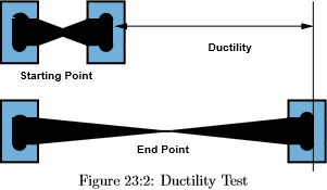
![By Leyo, Con-struct [CC BY-SA 3.0], via Wikimedia Commons](https://upload.wikimedia.org/wikipedia/commons/9/96/Aluminium_-_world_production_trend.svg)
#/media/File:AmunhotepIIIAndQueenTiye-MarriageScarab_BrooklynMuseum.png)
.jpg)
In the case of semiconductors, applying a voltage can boost the electrons across the gap. This would be like kicking one of the cars from the traffic jam over a medium to an unpacked highway. Thus, the semiconductor can be changed from being an insulator (off) to a conductor (on). We will look at one aspect of this behavior in the next section.
PN Junction
In a semiconductor, it is possible to dope the material with impurities that add electrons or holes to the semiconductors. (Think of the holes as adding more open spots on the freeway so that cars can move more easily.) When atoms with extra electrons are added, they are electron donors and the semiconductor is said to be doped to n-type. When atoms that accept extra electrons are added, they are electron acceptors and the semiconductor is said to be doped p-type. When p-type material is put together with n-type material you get the basic building block of the integrated circuit industry. Please watch the following video (10:36) on how p-n junctions work.
To Watch
Now let’s define nanotechnology and explore one possible application of nanotechnology which might allow for the continuing improvement in microprocessor speed in coming decades.
Introduction to Nanotechnology
Nanotechnology involves the control of atoms and molecules to produce materials in the size range of 1 – 100 nm, whose size or geometry dominates their material properties. Nanotechnology occurs in a size range were quantum mechanics dominate, but the materials are larger than a single atom. This size range is the range where single-atom behavior is transitioning to bulk material behavior. This allows for the tuning of properties to desirable results, which allows for the creation of designer materials. An example of this is gold nanoparticles. As shown in the figure below, nano-sized gold particles range in color from bright red, pink, purple, to blue, depending on the size of the nanoparticles.

So, how many atoms are we talking about when we say the material ranges from 1 to 100 nm in size?
A cube of 1 nm on a side would have around 100 atoms, while a cube of 100 nm on a side would have around 100 million atoms. That is quite a range. A former professor of this course, Dr. Peter Thrower, in his textbook Materials in Today’s World, calculated how many atoms would be on the surfaces of cubes of 1 nm (nanocube) and 1 cm (bulk cube). What he found was that in the nanocube, 60% of the atoms were on the surface of the cube. This was in stark contrast to the bulk cube, where only one out of 109 atoms were on the surface.
What does this mean chemically? Bulk gold is highly unreactive; it does not tarnish, it does not react with other metals, etc. It is so unreactive that it's possible to find gold in nature in its native state, gold nuggets. Nanogold, on the other hand, is extremely reactive. In bulk gold, the atoms are overwhelmingly non-surface atoms. These non-surface atoms have sufficient neighboring atoms to satisfy their bonds. In nanogold, most of the atoms are on the surface and possess unsatisfied bonds, which makes them extremely chemically reactive. This is a case where the size of the particle matters but also the geometry matters. In the case of nano gold, the geometry of possessing mostly surface atoms results in a chemically active material.
Introduction to Nanotechnology (Continued)
Nanotechnology, through the control of atoms and molecules, has the potential to create unique materials with wide-ranging applicability including the areas of medicine, smaller (faster) devices, self-assembled structures, and other designer materials applications. Nano materials are also allowing scientists to explore still unanswered fundamental materials questions. The field of nanotechnology is generally accepted to have been identified by Nobel laureate Richard Feynman during a futuristic talk entitled, "There’s Plenty of Room at the Bottom," in 1959. In that presentation, Feynman speculated about being able to write the entirety of the Encyclopedia Britannica on the head of the pin. On September 28, 1989, an IBM physicist, Don Eigler, became the first person to manipulate and position individual atoms. One example of his work is shown in the figure below utilizing 35 xenon atoms.

In the next section, we will look at how carbon nanotubes might allow for faster transistors in the future.
Moore's Law
According to Wikipedia, "Moore's law is the observation that the number of transistors in a dense integrated circuit doubles approximately every two years." Gordon Moore made that observation in 1970, and as you can see from the figure below, it has been remarkably accurate over the many decades since.

But you cannot just keep making things smaller and smaller to make them faster and faster. At some point, you hit the limit of approaching zero and the fact that it becomes incredibly expensive to produce incredibly small feature sizes. As shown in the figure below, a leading trade magazine, IEEE Spectrum, has reported that transistors could stop shrinking in 2021.

This will mean that faster computers will not be possible based on shrinking geometries. One potential approach, instead of increasing the density of transistors is the approach of making transistors faster by using carbon nanotubes. Electrons move much faster in carbon nanotubes than conventional semiconductor materials. A picture of a research carbon nanotube bridge is shown below.
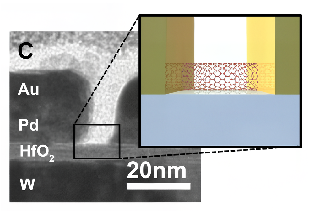
Reading Assignment
Things to consider...
When you read this chapter, use the following questions to guide your reading. Remember to keep the learning objectives listed on the previous page in mind as you learn from this text.
- What are the four possible electron band structures for solid materials?
- What effect does the electron band structure have on the electrical conduction of a material?
- What is a p–n junction, and how does it rectify current?
- What are the concepts of nanotechnology as it applies to materials?
Reading Assignment
- Read pp 323-347 (Ch. 15) in Introduction to Materials ebook
- The following readings are available in Canvas.
- Pages 245 to 251 (Chapter 32) of Materials in Today's World by Peter Thrower and Thomas Mason.
- Pages 253 to 255 (Chapter 33) of Materials in Today's World by Peter Thrower and Thomas Mason.
Video Assignment: Making Stuff: Smaller
Now that you have read the text and thought about the questions I posed, take some time to watch the 53-minute NOVA video about how the latest in high-powered nano-circuits and microrobots may one day hold the key to saving lives. In "Making Stuff: Smaller," we see how making materials smaller has the potential for making vastly improved and tailored materials for future materials applications.
Video Assignment
Go to Lesson 12 in Canvas and watch the Making Stuff: Smaller video. You will be quizzed on the content of this video.
Summary and Final Tasks
Summary
As our understanding, and control, of materials at the nanometer scale improves, we are able to manufacture materials that are: tailored for specific tasks, designed to perform at the extremes of materials properties, or can utilize structure to enable properties not achievable before. Utilizing bottom-up, self-assembly, and other novel fabrication techniques, designer materials are becoming possible for everyday usage. In fact, superior materials are known today, but their utilization is hampered by our current inability to mass produce usable quantities economically. In this lesson, we looked at the basics of electronics, as well as some of the basics of nanoelectronics, which has the potential of being the electronics of the very near future.
Reminder - Complete all of the Lesson 12 tasks!
You have reached the end of Lesson 12! Double-check the to-do list on the Overview page to make sure you have completed all of the activities listed there before you take your final.