Lesson 9.1: Orebody Access
Lesson 9.1: Orebody Access
There are three common methods to access an orebody under deep cover. They are shafts, declines, and adits/drifts.
Shafts
A shaft is a vertical or nearly vertical opening driven from the surface to the deposit. The cross-section of a shaft is usually elliptical or circular, as these shapes are stronger than square or rectangular openings, provide less resistance to airflow, and maximize the useful space per dollar spent on the shaft. The diameter or dimensions of the opening are based on the purpose for which the shaft will be used, and the diameter can commonly range from around 6’ to 30’, and sizes outside of this range occur occasionally. The shaft may be used solely to hoist ore to the surface, provide ventilation, or to transport people and supplies. Commonly, shafts are partitioned and serve more than one purpose.
Declines
A decline can take the form of a slope, which is a straight opening driven at an angle, or a ramp, which is similar to a slope except that it is generally helical in shape. The angle of the slope, as well as the design radius and the angle of the ramp, depend on their intended use. The dimensions of a decline will depend on the purpose for which it is to be used. A slope may be outfitted with a belt conveyor to move ore out of the mine, or perhaps there will be track for rail haulage. The slope may be partitioned with a top and bottom compartment to facilitate multiple uses, including ventilation. A ramp, on the other hand, is used primarily for access, to move people, supplies, and ore between levels or to the surface, and it will be sized to accommodate the largest piece of equipment in use. The ramp may also be used for ventilation and utilities, e.g., electric power cables and water lines.
Adits/Drifts
Openings that are driven within the ore and follow the seam or vein are known as adits when they are driven in metalliferous veins or drifts when driven in coal and nonmetal seams. Functionally, there is little difference between a slope and a drift or adit. It’s simply that one, the slope, is driven in the country rock, i.e., the nonmineral-bearing rock around the ore, whereas the other, the adit or drift, is driven in the ore. In the past, it was common to find veins or seams that intersected the surface. The practice, as you would expect, was to begin mining the ore where it intersected the surface, and then to follow the vein or seam and continue mining. In some cases, this led under a mountain, in other cases, with a vein or seam that was dipping at some angle, the driven opening could go quite deep. Regardless, the opening at the surface, or the entry point into the mine, is known as an adit or drift. Thus, when you hear the term slope, you will know how that differs from drift or adit. To be honest with you, I find some of these definitions and the subtle differences among them to be a bit tedious. But, they are in common use, and you should know what they mean, and you should use the correct term.
And number 4: the Box Cut
There is a fourth means of access that is used infrequently, but is common enough to warrant its own category. It is known as a box cut. You may recall learning this term earlier, as this term is taken from surface mining, and specifically the open cast mining method known as area mining. In that method, an initial cut is made to start the process, and the material from this cut is hauled away. Typically, this cut looks like a box: it is few hundred feet wide and several hundred feet in length, and may be up to a few hundred feet in depth. However, the dimensions are specific to the application. You’ll find this method of access being used in coal and limestone, and often the depth of the box is less than 100’. The idea is to have the floor of the box at the same level as the seam. This allows openings to be driven into the seam. And what would these openings be called? Yes, drifts. Of course, roadways need to be constructed to allow equipment, supplies, and personnel to be transported down into the box cut, and into the mine. Sometimes, the box will be enlarged to allow placement of buildings, crushers, and so on within the box cut.
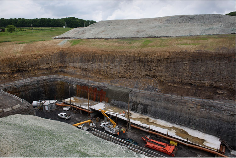
Here is a photo of a box cut to access a coal seam. You can see the overburden that was removed and carefully place in the background. Note the overburden layers and the rock overlying the coal seam. In the front left side of the picture is an access road into the box, although it is difficult to see clearly.
The choice of an access method is generally limited. The following list illustrates the factors that go into the selection.
- If the seam or vein intersects the surface, a drift or adit will be the choice.
- If the seam is close to the surface, i.e., typically within a few hundred feet, a box cut will receive serious consideration.
- The construction cost of a shaft is about three times the cost of a slope; however, the construction footage of a slope is generally at least three times that of a shaft.
- The deeper the orebody, the more likely that a shaft will be used.
- Transporting large equipment into a mine is more easily accomplished with a slope rather than a shaft. Large equipment must be cut into pieces and reassembled underground if there is no slope access.
- Construction of a slope is more challenging in difficult ground conditions, and could sway the decision to choose a shaft.
- A shaft limits the materials handling to batch operations, which is a serious limitation, as discussed earlier in the semester.
- Quite a bit of real estate is required to put in a slope, and a ramp can be constructed under a much smaller surface footprint.
- A ramp precludes continuous haulage, which can be a disadvantage.
- Coal mines require two means of access, and it is common for deep mines to use both a slope and a shaft. This allows them to realize the benefits of both means of access.
This is not an exhaustive list of considerations, but it is representative. As you progress in your studies and learn more about ground control, ventilation, and materials handling, the decision criteria will become even clearer to you. These openings must serve as primary conduits for ventilating air – either fresh air intakes or exhaust air returns, and that will impact the size and configuration of the choice. The material handling options, which center around batch versus continuous, will be important factors in the decision, as well as the need to move very large equipment on a regular basis. You’ll recall from our discussion of auxiliary operations that we have several materials handling options. These can be summarized here by access type.
| Shaft | Slope/Drift/Adit | Ramp | Box Cut |
|---|---|---|---|
| Hoist | Rail | Rubber-tired haulage | Rail |
| Vertical belt | Belt | Belt | |
| Elevator | Inclined hoist | Rubber-tired haulage | |
| Rubber-tired haulage |
Placement of the Access Opening
What about the placement of the access opening on the property? All things being equal, you’d probably want the access to be near the centroid of the orebody. The location of roads and rail service to your property could affect the decision, as could topography. You wouldn’t want your shaft to be located at the lowest natural drainage point of your property, and permitting constraints limit the placement as well. In general, you cannot place an access opening down dip from the seam that you are mining because any water accumulation in the mine would then drain out of the mine. That can be an environmental issue that you have to address. Ground conditions may affect your placement decision as well. Unless there are overriding circumstances, logistical considerations will weigh heavily in your decision of where to locate the shaft, slope, ramp, or box cut.
9.1.1: Construction of the Access
9.1.1: Construction of the Access
We should talk a little bit about the construction of these means of access. The construction of the drifts, adits, slopes, and ramps does not differ significantly from the unit and auxiliary operations for mining the ore, which we discussed previously. However, these access openings are generally, except to remain serviceable for the life of the mine, unlike many of the other workings that are in use only while the ore in that part of the mine is being exploited. Consequently, extraordinary measures can be justified to ensure the stability of these openings over many years. What are these measures? Reinforced concrete liners, steel arches, and/or additional rock and cable bolts to ensure long-term stability. Some rock types deteriorate when exposed to moisture, and you may shotcrete these surfaces to prevent oxidation and deterioration.
Shaft sinking, on the other hand, may involve some operations and equipment that we didn’t address directly in our study of unit and auxiliary operation. Shaft sinking can be accomplished with a conventional cycle, i.e., drill-blast-muck-hoist, or a continuous cycle using a blind-shaft boring machine. Let’s talk about each cycle.
Previously, we talked about the conventional cycle used in mining as consisting of the unit operations: drill-blast-load-haul. The same unit operations are used to sink a shaft, but the name for loading has changed to mucking and the name for hauling has changed to hoisting. As we sink a shaft into the earth, we cannot load the blasted material with a wheeled loader for example and haul the blasted material off to a dump… obviously! Instead, we use a clamshell mucker to grasp the broken rock and drop it into a large hoist bucket. When the bucket is full, it is hoisted to the top of the shaft and dumped into a waiting truck, where it will be hauled to a dump pile. Hence, the name change for loading to mucking and hauling to hoisting in the conventional cycle for sinking a shaft. It should be noted that the word muck refers to any broken, i.e., blasted, rock, and the word mucking is an old mining term for the operation of loading out muck. Here is a video illustrating the mucking and loading operations in a shaft. This example is for a fairly shallow and small shaft. Larger and deeper shafts involve more complex arrangements, consisting of multiple deck stages and equipment. Nonetheless, this video (2:28) illustrates the basic concept.
During the sinking of the shaft, the auxiliary operation of ground control is generally crucial. The first tens or even a hundred or more feet are driven in relatively poor quality material, e.g., soils and weathered materials that will not stand on their own. In other words, they would tend to fall into the shaft. In areas of past glaciation, the overburden may consist of a hundred feet or more of loosely consolidated rubble. In these areas, the only way to sink a shaft is to freeze the overburden, drill and blast through the frozen material, and then immediately place a liner in the shaft to support the shaft walls. Glaciers made it as far south as Illinois, for example, and so, if you want to sink a shaft down to a coal deposit in the Illinois basin, chances are good that you will have to freeze the alluvial till, i.e., the unconsolidated overburden. Freezing is accomplished by drilling and placing refrigerant pipes around the location of the future shaft, setting up a large refrigeration system, and pumping coolant through the pipes until the ground is frozen. Then, the shaft sinking can begin. Here is a good video (4:37) to illustrate a shaft sinking process in which freezing the overburden is part of the project.
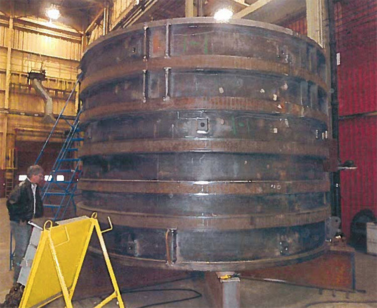
The ground support to maintain the integrity of the shaft walls may consist of rock bolts and wire mesh, but will normally require the use of liners. The liners could be timber, which was used in the past, mortared brick liners, which are also a thing of the past, or most common, concrete liners. In most cases, the concrete liners, a foot or more in thickness, are poured in place. Sometimes, precast liner segments are delivered to the site and set into place, and then a grout is pumped behind the liner to fill the space between the rock wall and the liner. The liners will change over the depth of the shaft depending on the need. If there is a problem with ground water infiltration, steps will be taken to seal the shaft in the water-bearing horizons. This is not as simple as it may seem. At depth, the hydrostatic pressure on that water could reach 500 to 1000 psi or more! To withstand these forces, specially constructed steel liners are used. They may be made out of steel that is ½ to 1” thick, and then welded into place with a concrete ground pumped behind the liner to fill the void between it and the shaft wall. Here’s a picture of such a liner in the shop prior to delivery.
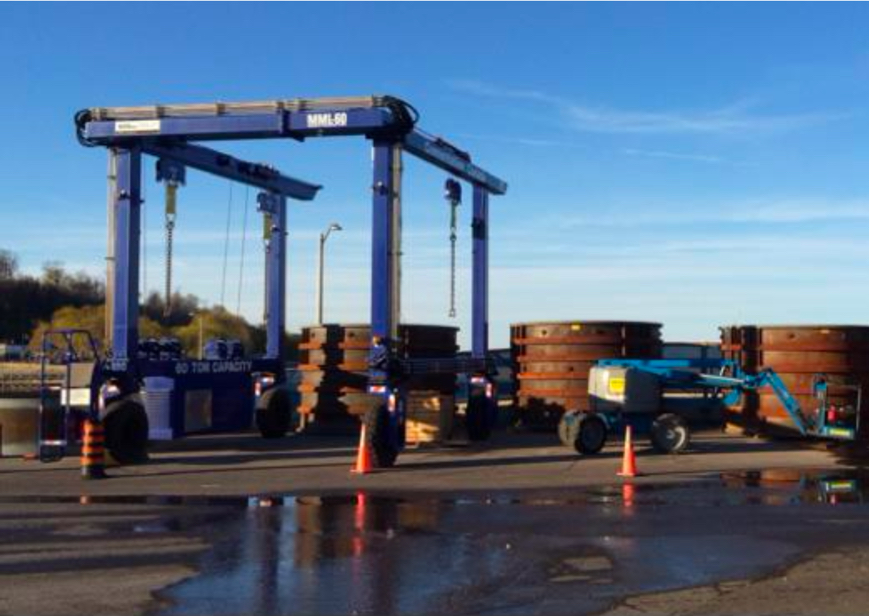
And here is a picture on site. You can see the liners waiting to be installed, along with the gantry for lowering them into the shaft. In this case, they are being set in the first 900’ of the shaft.
9.1.2: Revisiting "The Quest for Continuous"
9.1.2: Revisiting "The Quest for Continuous"
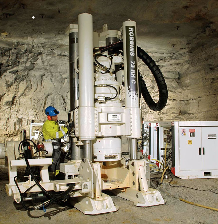
In a previous lesson on “the quest for continuous,” we looked at the motivation for replacing conventional cycles and the equipment for doing so. In the case of shaft sinking, the same principles have been applied. A variety of boring machines has been developed, and consist of a rotating and bit-laced head, a built-in materials handling system to clear the cut material and send it on its way to the surface, and the means for advancing, guiding, and controlling the borer. Likely, there are stages immediately above the borer that are outfitted to allow placement of liners. The following video clip (10:35) provides a detailed look into the functionality of a modern shaft boring machine.
In soft to medium harness rock, the boring machine is the preferred choice, as it can be done faster and at a lower cost than with conventional methods. However, in hard materials, a conventional drill and blast cycle is the only viable choice. This is similar to what we find for continuous mining methods in various deposits. There is one other machine of note for smaller diameter shafts – the raising boring machine.
Small diameter shafts, say less than 10’ in diameter, are required in many applications. They are used for emergency escape hoists, ventilation shafts, and travel ways between levels in a mine. The latter are known as raises, and this is where the name, raise borer, originated. In the good old days, raises and small diameter shafts were driven using conventional cycles. Today, a continuous cycle is used in most cases.
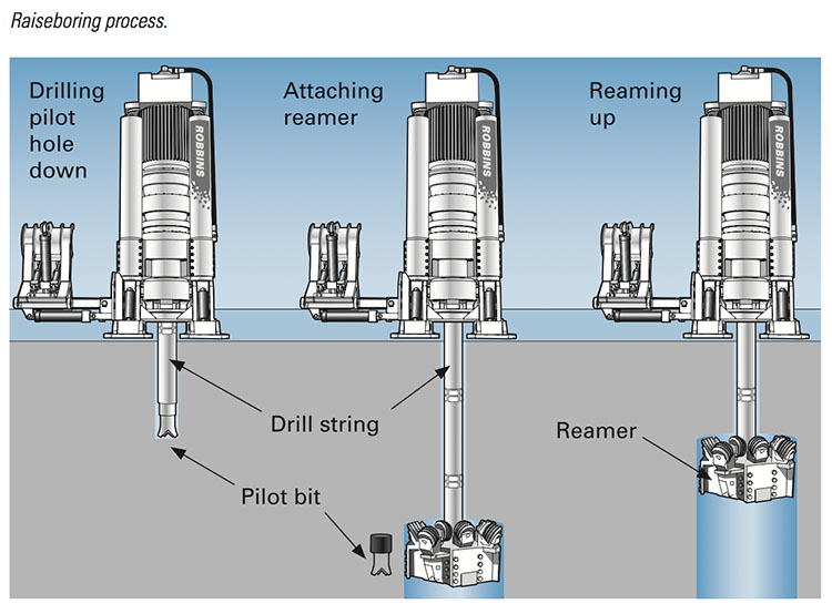
Raise boring requires that the bottom of the raise terminates in an existing mined opening. The first step in using a raise borer is to drill a pilot hole down to the exiting opening. Once completed, a large diameter cutting head is threaded onto a drill steel that connects to a power source on the surface or the upper level. The power source, i.e., the raise borer, provides thrust and rotation for the cutting bits. The cuttings fall to the lower level where they must be loaded and hauled. Take a look at this figure – it makes more sense if you can see it!
Here is a picture of the power unit. Raise borers can excavate an inclined open as well as vertical, and they can bore upward, although that is done with less frequency.
9.1.3: Odds and Ends
9.1.3: Odds and Ends
There are a few odds and ends – points that need to be made, but which I haven’t discussed until now. I’ll finish out this lesson by covered these.
The shaft collar is the name given to the point where the shaft intersects the surface, and it is also a structural component of the shaft. It is typically reinforced concrete and it will be either anchored into bedrock or tied into a liner that is anchored in the bedrock. The collar serves an important structural function for equipment associated with the shaft, and it is used to limit surface drainage into the shaft.
A building or structure is associated with the shaft. If there is a hoist, there will be a headframe. Hoists are always used to haul ore up the shaft and out of the mine. The hoist may also include a cage. This is a steel structure, typically with open steel mesh construction, giving it the name “cage” used to transport miners and supplies. The trip to the bottom or back up to the top is known as a mantrip. In deep mines, the cage will likely have multiple floors so that a hundred or more miners can be transported at one time. When it takes 15 to 30 minutes to make the descent, you want to minimize the number of trips! Hoists are of two general types: drum or Koepe (friction hoist). You will learn how to design both in MNG 404, and we won’t go into the differences here, although they are discussed in the text. If there is no need for a hoist, i.e., to transport ore, but only a need to transport people and supplies, then an elevator would normally be used. The elevator is similar in construction to one that you would find in a high-rise office building of 100 stories.
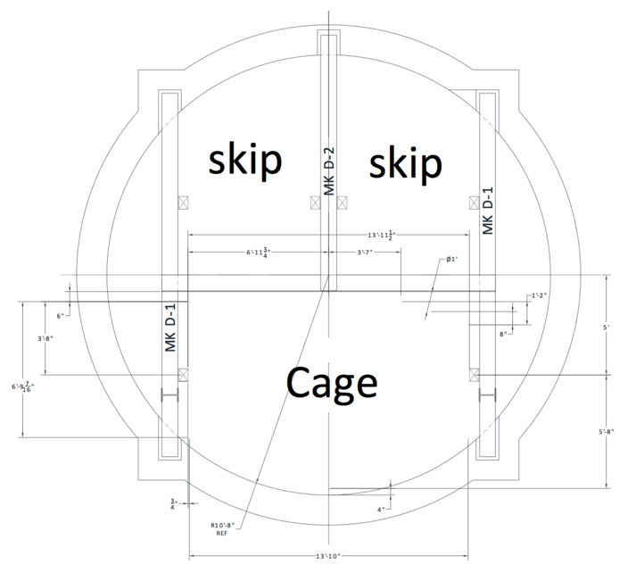
Here is a cross-section of a shaft showing the compartmentalization or multi-function layout. Half the shaft is dedicated to hoisting ore, and there is a skip at the bottom and a skip at the top of the shaft. As one skip is being unloaded at the top, the other is being loaded at the bottom. For reasons that will become clearer later on, this is a Koepe hoist. The other half of the shaft is dedicated to a cage. This cage is connected to a drum hoist. You might want to think about why the Koepe hoist is used in the one case and the drum hoist in the other.
Shaft development practices have changed over the last few decades, with bored shafts being much more common and the "circular" shaft becoming all but universal for large shafts in new mines. In coal mining, about half of all shafts are now sunk by blind-boring methods. It has become common for main shafts up to 16’ to be drilled in this fashion. In addition, many coal mining companies now use bleeder shafts to simplify their longwall ventilation systems. These are sometimes drilled using blind-boring rigs. Raise-bored shafts are done as well, but access must be available underground to make this feasible, and the need for a mucking and transportation system underground makes this alternative less favorable. For large shafts, greater than 20’, in coal mines and for most metal and nonmetal mine shafts, conventional shaft-sinking methods are still commonly used.
We’ve talked little about slopes and ramps because their construction differs little from the conventional mining cycle. However, it should be noted that tunnel-boring machines are being used with increasing frequency to drive large slopes of considerable length. The cost of bringing a tunnel boring machine to a site, and setting it up is very high, and can only be justified for large diameter slopes that are greater than a few thousand feet.
The slopes used in today's coal mines are normally driven with two compartments: an upper compartment to accommodate a belt conveyor and a lower compartment containing track that is normally used for personnel and supply transport. The two compartments are separated by a horizontal concrete divider and are supported by bolts, wire mesh, or steel arches. Slopes in coal mines are often horseshoe-shaped, with widths of 17 to 20’ and heights of 13 to 14‘.
The next lesson will address the "building blocks" or basic elements of underground mines. Once we have gained access to the deposit, we are ready to begin development of the underground workings. We'll be introduced to the elements of those workings in the next lesson, and after that, we will be prepared to examine the development of underground mines for the different mining methods.
Before moving on, use these interactive activities to test your knowledge of important terms in this lesson.