Lesson 9.3: Mining by Unsupported Methods
Lesson 9.3: Mining by Unsupported Methods
You will recall from Lesson 4.3 of Module 4 that underground mining methods are traditionally placed into three classes: unsupported, supported, and caving methods. These classes reflect the competency of the orebody and host rock more than anything else. If you excavate an underground opening in the ore or the rock, is the opening stable -- i.e., will it remain open for an extended period, or will it begin to fall in? If it is unstable, i.e., the surrounding ore or rock breaks up and falls into the opening, how much support would be required to keep the opening from caving in? The answers to these questions lead us to choose mining methods from one of the three classes.
We are going to focus on the class of unsupported methods in this lesson. If the rock is essentially self-supporting and only requires the addition of minimal artificial supports to achieve a stable opening, then one of the methods from the unsupported class will most likely be applicable.
The three important methods within this class are room and pillar, shrinkage stoping, and open stoping. After a brief summary here, we’ll look at each in more detail. We will not talk in detail about the unit and auxiliary operations associated with these methods, as these were covered earlier in the course. Suffice it to say that a conventional mining cycle is used for shrinkage stoping and open stoping, whereas both continuous and conventional cycles are employed with the room and pillar method, depending on the commodity being mined. Examples of commonly used equipment will be noted for the different methods.
Room and Pillar Mining
This method of mining is used to recover bedded deposits that are horizontal or nearly horizontal when the orebody and the surrounding rock are reasonably competent. Parallel openings are mined in the ore, i.e., rooms, and blocks of ore, i.e., pillars, are left in place to support the overlying strata. Other than the pillars, little artificial support is required and often consists of bolts placed into the overlying strata to pin the layers together, making them behave like a strong laminated beam. A few examples of commodities mined by this method include coal, lead, limestone, and salt. Historically, if the pillars were irregular in size and placement, which is more likely to occur in certain metal and nonmetal deposits, this method was known as stope and pillar, rather than room and pillar. You will still hear the word stope and pillar being used, but the distinction is now largely irrelevant. This method accounts for the vast majority of all underground mining in the U.S. – and I believe globally as well, although I have not done that analysis. Examples of commodities mined by this method include coal, limestone, salt, trona, lead, and potash.
Shrinkage stoping
Shrinkage stoping is used to recover steeply dipping orebodies when the ore and host rock are reasonably competent. A stope, i.e., a large section of the mine where active production is occurring, is mined, but the broken ore is not removed, but rather is left in place to support the walls of the stope until the time when all of the broken ore will be removed. Since rock swells, i.e., increases in volume when it is broken, it is necessary to draw off some of the broken ore as the stope is progressively mined. The name of this method derives from this drawing off or shrinkage of the stope. A modern and important variant of this method is known as vertical crater retreat (VCR) mining. A few examples of commodities mined by this method include iron and palladium.
Open stoping
This type of mining is used to recover steeply dipping orebodies in competent rock. The ore is removed from the stope as soon as it is mined. Sublevel stoping and big-hole stoping are the important variants in use today. A few examples of commodities mined by this method include iron and lead/zinc.
9.3.1: Room and Pillar Method
9.3.1: Room and Pillar Method
Room and pillar mining is arguably the most important underground mining method in practice today. The majority of underground production comes from room and pillar mines, and the majority of underground mines, by number, employs the room and pillar method! Think about that!
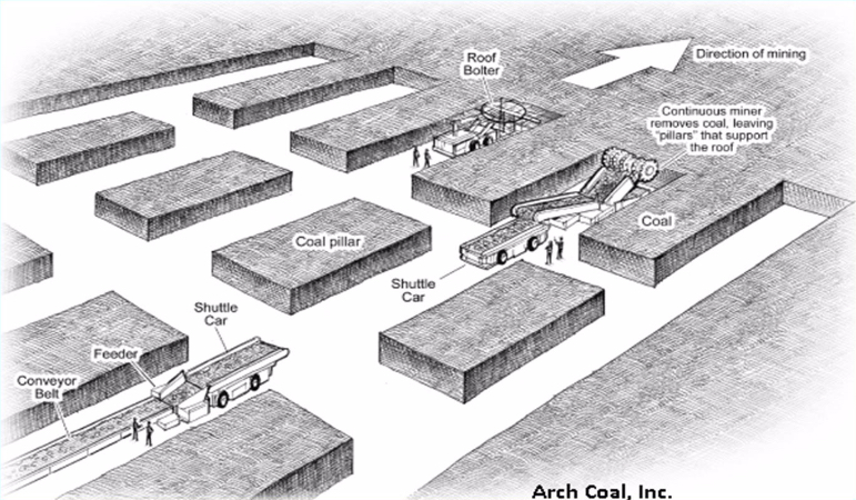
Let’s start out by looking at this sketch of a section in a room and pillar mine. Immediately, you can see that only part of the deposit is mined. Openings are driven in the direction of mining, as shown, and unmined pillars are left in place to support the overlying strata.
Remember from our earlier discussion of ground control: when we mine an opening, the weight of the overlying strata must be supported; otherwise, it will cave. As long as the rock layers over the opening are sufficiently strong (think beam), the weight of the overlying members will be transferred to the points where the beam is supported. Those points are the pillars. And from an engineering perspective, it is essential that you do not make the beam too long, because if you do, the beam will fail in the middle, and you will have a cave-in. Just to make it more interesting, you should know that in addition to choosing an appropriate opening width, which is governed by the allowable span of your beam, you also have to worry about the pillar. In some cases, the pillar is not strong enough to bear the weight being superimposed on it, and it will fail. And, in some cases, the pillar will be sufficiently strong, but the layers comprising the floor will not be, and the pillar will push through the floor. Lots of things to think about! This is one reason why, if you are going to be a mining engineer, you will take a course in rock mechanics and cover ground control design in the underground and surface mining courses.
Anyway, back to our sketch of the room and pillar section. The diagram shown is labeled specifically as a coal mine. In fact, it could just as well be salt, trona, lead, and so on; but with some differences that we will discuss. The active mining areas of coal mines are known as sections. In this diagram, you see one working section. This section consists of the equipment and personnel required to conduct the mining activity. From our earlier discussions of unit and auxiliary operations, you will recognize this as a continuous mining operation; and in the U.S., there are no remaining conventional mining sections in underground coal mines.
The mined-out areas in the sketch are given special names, and these may vary depending on the type of deposit that is being mined. There is one term of special significance: the mined-out areas in the direction of mining are known as rooms. Hence, the name of the mining method, room and pillar. Very clever… Typically, the pillars are laid out in this regular checkerboard pattern in coal mines, and now in most other commodities as well. That was not always the case for the noncoal mines. The size, spacing, and even location of the pillars would vary significantly, as would the dimensions of the openings. In those mines, the method was known as stope and pillar. Although you will still hear the term being used, the distinction has largely disappeared, and the term room and pillar is normally applied across all deposit types employing this general method. As a point of interest here, I would mention that mining engineers now recognize that there are serious shortcomings to the somewhat random placement of pillars, resulting in unnecessary ground failures, e.g., cave-ins. As a result of the art and science developed in underground coal mines, ground control approaches such as the pressure arch approach are more generally applied in all commodities, and this results in a more uniform placement of pillars. You will learn more about this if you take a rock mechanics course.
I want to talk about a few more terms. We’ve defined rooms and pillars. The openings driven between rooms are known as crosscuts. Here, they are shown at an angle of 90 degrees, and that is common; but if you are using continuous haulage, such as the flexible conveyor trains that we covered earlier, then you’ll be driving the crosscuts at a different angle of say 60 degrees. Recall also, that the point at which the material is being freed from the deposit is known as the face. In the sketch, you can see five faces. The continuous miner is mining at one face, and a roof bolter is bolting at another face. Alright, there are just a few more terms, and then we fill in some additional detail for the method itself. Let’s look at this plan view of a room and pillar section.
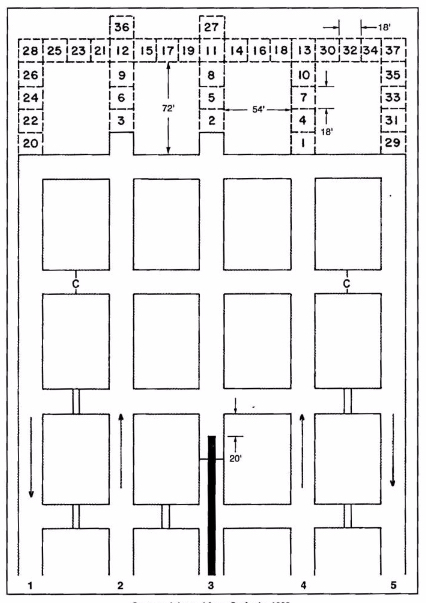
The sequence of rooms in the direction of mining is known as an entry in a coal mine. They take on the appearance of well-laid-out streets in a city. Indeed, you can stand in an entry and see for quite a distance. If you are in a noncoal mine, you may refer to entries as well, but more likely you’ll call them drifts or headings. What about the sequence of crosscuts? What special name do we assign to that? We don’t assign a special name, and the primary reason is that they do not form a continuous path in the way that rooms do for entries. The reason for that will become clearer within this lesson.
The collection of rooms and pillars shown in this figure form a panel. In this case we have a five-entry panel. Depending on the mining plan this panel could be 10,000’ or more in length, but its width will be determined by the width of the pillars and entries. Three-entry panels are common, as are four and five. There are additional details of note on the plan view.
- There are two different symbols, which appear in the cross cuts: the double line is a solid barrier known as a stopping, and often constructed of concrete blocks; and the single line with a “C” is a flexible curtain, known as a check curtain. Both of these are used to route and separate ventilating air. Recall that you need to provide fresh air to the working places, and then you need to exhaust the air that has become fouled with dusts and gasses.
- The directional arrows are illustrating the direction of the ventilation streams, sometimes called air courses. The air moving toward the face is known as the intake, and the stale air that has already passed the working face is known as the return.
- The thick solid line in entry number three is the conveyor belt.
- The numbered blocks are representing a cut sequence, i.e., block 1 is mined and then block 2, and so on. The cutting sequence will vary by mine, so you don’t need to know this cutting sequence. Simply, it is illustrating that there is a pattern to be followed. This pattern will be designed to optimize productivity and safety.
- The dimensions that are shown will vary somewhat by mine and certainly by commodity; and again, you don’t need to remember these specific numbers.
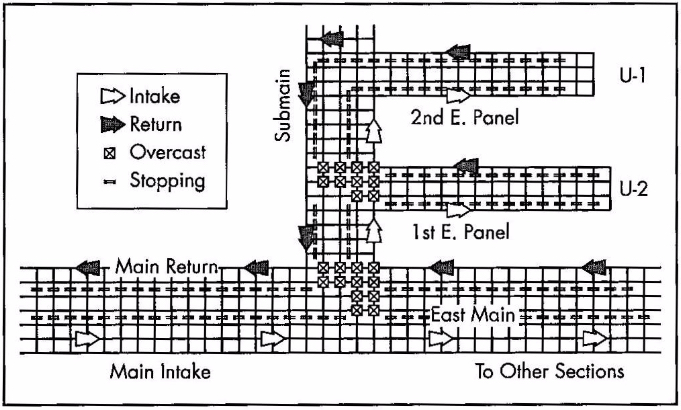
Finally, in terms of this overview, let’s look at this next figure. Notice that we are no longer representing the entries and cross cuts the same way. We’ve replaced them with a single line. That makes it easier and faster to draw these diagrams. As you look at this figure, you will see some of your newly acquired concepts, including Panels, Sections, Intakes, Returns, and Stoppings. There are also three new terms: overcasts, mains, and submains. Overcasts are yet another type of ventilation control joining curtains and stoppings as controls to route ventilating air. Specifically, overcasts are used to route on type of air over tip of another. It’s similar to a pedestrian overpass to allow people to walk over top of a busy highway. The overcast allows us to route, for example, intake air over top of a return aircourse without mixing the two airstreams. To satisfy your own curiosity, go ahead and trace the airflows in the part of the mine represented in the figure.
Now, on to the two other terms that I really wanted to highlight in this figure: the mains and submains. These are common terms in every coal mine and in some industrial mineral mines, e.g., trona. These words are simply designating their importance in the overall mine plan. The mains serve as the primary means of distributing utilities throughout the mine as well as being the location for the primary transportation and materials handling routes. The submains branch off of the mains to provide these same services to a group of panels, and the panels of course are the location for the active production sections. These word, mains and submains, and sometimes panels, are used as adjectives as well as nouns. The major aircourses supply air for the mine are known as the main intakes and main returns, for example. Main haulage of the mine may be a 72” belt, whereas the belts in the submains may be 60”, for example. It is no coincidence that the mains have more entries than the submains, which usually have more entries than the panels. Mains with seven to eleven entries are common. Often, three or four parallel entries are required to serve as intakes in larger mines, with two or three parallel returns, and another two isolated entries for material handling -- one being a belt entry and the other a track (rail) entry.
We now have a basic understanding of the layout for room and pillar mines, and we know the key terms that are used to describe them. We also know either continuous or conventional production cycles can be employed. With this as a solid foundation, let’s complete the picture with the conditions necessary to use a room and pillar method.
This is an underground method for which you can find mines as shallow as 60’ and at depths of greater than 2500’, and so we can conclude that depth is not a particular defining characteristic for the use of this method. The method does require tabular deposits, as opposed to the porphyry or vein deposits; and further, the method requires that the ore be fairly uniform in quality and thickness. Those are defining characteristics. Deposits with little dip (< 15) are necessary, and less dip, the better. There are rare examples of room and pillar being applied to steeply pitching (dipping) coal seams, but they need not concern us at this time. The rock strength needs to be moderate to strong. The rock needs to be strong enough to allow a reasonable span of opening between pillars. The ore strength on the other hand is not quite as important in the choice of the method. As the ore strength declines, it will be necessary to leave larger pillars, and at some point, that becomes uneconomical. In real-world situations, however, the ore strength is rarely an important characteristic for the selection of this method.
Before reading on, please pause for a minute and think about the characteristics that will lead you to select or exclude the room and pillar method from consideration. Specifically, think about the relationship between that characteristic and the design or operation of a room and pillar mine.
I identified the shape of the deposit as important in the selection of this method, and I said that uniform thickness is desirable. In fact, the thickness can vary by 10 or 20%, and not eliminate room and pillar as a viable method. In some cases, the quality of the ore declines rapidly as you approach the interface between the ore and host rock. In those cases, it is not unusual to leave anywhere from several inches to several feet unmined. In still other instances, the competency of the rock in the immediate roof may be very poor, and in those cases, that material will be mined along with the ore. Yes, that will dilute the run-of-mine product, but the additional cost of doing so, may be less than the cost of the ground-control problem that would result from attempting to leave the “bad” roof layer in place.
I did not say anything about the thickness of the orebody. Room and pillar is used successfully in deposits as thin as 24” and as thick as 100’ or more. It is clear that the orebody thickness is not a defining characteristic of the method itself. However, the mining plan and cycle will be affected as the thickness increases. Consider this: you have a continuous miner with a reach of say 15’. Your seam is 25’ thick. How you are going to mine that seam? Are you going to take 15’ out of the 25’, perhaps down the middle, and leave the remainder? Although there might be an instance in which you would do that, generally you would not invest the capital to access the orebody, and then voluntarily leave a lot of it behind! So, back to the question… what are you going to do?
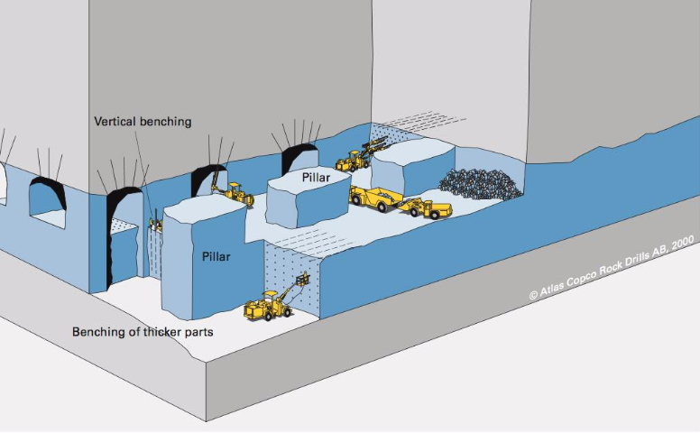
Why not take it out in layers? That is what we do, and we refer to it as benching. We can do this, and it is frequently done with the continuous or conventional cycles. In some instances, both are used, i.e., the top lift or bench is taken with a continuous cycle and the bottom bench is taken with a conventional cycle. In these thicker seams, three of more lifts may be taken. Take a look at this figure.
It is apparent that the first bench is taken at the top of the deposit. This is the norm for room and pillar mining. For one thing, it is easier to scale and bolt the roof form this first bench. This figure is illustrating a conventional cycle, and we can see a couple of interesting practices. Note the drifting or breast stoping occurring on both the top bench and on the lower bench right side. As a contrast, look at what’s happening on the left side and front of the top bench: underhand stoping. They are also showing some overhand stoping, but, to be honest, I have no idea why! If they were moving upwards in the orebody that would make sense… Just ignore that part of the figure! Anyway, this is a good example of benching used in room and pillar mining.
A defining characteristic for the selection of the room and pillar method, as I explained earlier, is a relatively flat lying deposit. What if you meet the characteristics of the unsupported class of methods, except that you have a steeply dipping orebody? You will look more closely at selecting an open stoping or shrinkage stoping method. Next, we will look at these two unsupported methods that are only applicable to steeply dipping deposits that are greater than 50 degrees, and frequently near vertical. The dip angle of the footwall must be greater than the angle of repose for the broken ore because these methods depend on gravity flow to collection points (draw points).
9.3.1a: Typical Equipment
9.3.1a: Typical Equipment
Before moving on to look at the methods suited for these steeply dipping deposits, I do want to identify some typical equipment used in room and pillar mining. There is a significant variation in equipment usage across room and pillar mines. This should not surprise you, given the big differences in the deposits. As you might expect, the equipment used to mine a 5’ thick coal seam is quite a bit different than that used to mine a 50’ thick lead-zinc deposit.
| Continuous Cycle | Conventional Cycle |
|---|---|
| Continuous mining machine | Jumbo drill |
| Road header | Wheeled loader |
| Shuttle car | Haul truck |
| Flexible conveyor train | Mine truck |
| Roof bolter | Scaler |
| Roof bolter | |
| Powder loader |
In the list of “typical” equipment, you saw an item that has not been discussed yet. A rock duster, which is an essential piece of equipment for an auxiliary operation in underground coal mines. Given the importance of this auxiliary operation to underground coal mining, let’s say a little more about the need for it, and the practice of rock dusting.
After we conclude our discussion of rock dusting, we’ll resume with the unsupported methods of shrinkage and open stoping.
9.3.1b: A Practice and the Auxiliary Operation to Prevent Explosions
9.3.1b: A Practice and the Auxiliary Operation to Prevent Explosions
Fine dust that is suspended in the air can be very explosive. Coffee, coal, cotton, and flour are important examples of dusts that are explosive, and are examples of deadly explosions that do occur in industrial settings. Many processes that involve milling, grinding, and cutting, for example, can generate fine dust particles. Under the right conditions, they can fuel powerful explosions.
Fine basically means that the dust particle has a very large surface area to volume ratio. We all have practical experience with fine dust. If there is sunlight shining into your room, pick up a towel, sheet, or piece of clothing and shake it. What do you see? Dust particles floating in the air, right? Eventually, those dust particles settle onto your desk or other furniture, and then periodically you take a cloth a wipe the accumulated dust away. There are corollaries between your practical experience and the industrial issue with dusts, and we will identify them.
The dust particles that are suspended in the air, and then eventually settle are known as float dust. The exact size of the float dust is somewhat dependent on the material. For coal dust, we are interested in particles that are 75 microns or less in size. The cutting action of carbide-tipped bits, as used in continuous mining machines, and shearers, creates not only large pieces of coal, but also a range of much smaller particles. Some of these are less than 10 microns and are respirable, i.e., they are trapped in the lungs when we breathe air containing these particles. Long-term exposure to excessive concentrations of respirable dusts will lead to fatal lung diseases, e.g., black lung (coal) or brown lung (cotton). The concentration of respirable dusts is heavily regulated, and engineering controls are used to ensure that hazardous concentrations do not occur. As we’ll see, the concentration of float dust is regulated as well. The creation of these dusts is an unavoidable consequence of the cutting or processing of the materials. Therefore, if we want to avoid bad outcomes, we have to take steps to ensure that the dust does not cause harm.
Before we can mitigate the affects of float dust, we need to know a little more about the genesis of dust explosions. In general, we must satisfy three conditions to have an explosion. We need a fuel, an oxidizer, and an ignition source. In this case, the dust serves as the fuel and the oxygen in the air serves as the oxidizer. Ignition sources can be varied. A spark created when a carbide bit strikes a hard rock at the interface of the coal seam and the roof, a spark from a motor or piece of electrical equipment, or in the old days, a match used to light a cigarette. It takes a very small amount of energy to ignite a dust cloud, or for that matter, a methane-air mixture. Given this information as background, what can we do to prevent a dust explosion?
Well, we have three choices, don’t we? Eliminate the fuel, the oxidizer, and/or the energy source. We can’t eliminate the oxygen, because it is in the air that our miners are breathing. We can’t eliminate the fuel, or can we? We can eliminate the energy source, so let’s talk about that one first.
We can ban the use of smoking materials in the mine or plant. In coal mining, smoking was banned with the 1969 Coal Mine Safety Act. This eliminated many explosions in coal mines. Next, we can mandate the use of special electrical equipment. We can require that all electrical equipment used in certain areas be placed inside of explosion proof enclosures. Unfortunately, no one has devised a way to prevent frictional ignitions, i.e., when a cutting bit creates a spark when striking certain rock masses, such as quartz or pyrites. Dramatically reducing the likelihood that an energy source will exist is doable; but guaranteeing that there will never be an energy source is not. Therefore, we have no choice but to try to eliminate the fuel source. While it is impossible to complexly eliminate the fuel source, we can dramatically reduce the chance of satisfying the three concurrent conditions necessary for an explosion, if we dramatically lower the likelihood of two of the conditions.
We cannot stop the generation of float dust, although researchers are attempting to devise ways to control it at the source. We can take two important steps after it has been created. Before talking about those steps, let’s first look at the anatomy of a dust explosion; and I need to preface that discussion with this fact: dust explosions follow from a methane explosion. We will use that as our starting point.
- A small volume of methane is ignited, perhaps by a frictional ignition. 99.999% of the time, our properly engineered and operated ventilation system is diluting the gas as it is liberated during cutting, and the ignition amounts to no more than a “little pop and flash of light.” If there is a little more methane present, the initial ignition will grow in size. High temperatures are produced and the gas and surrounding air will rapidly expand. The force of this explosion and the attendant damage will depend on the volume of methane present. We take significant steps to prevent the presence of an explosive mixture of methane and air, but sometimes multiple people fail to perform their responsibilities, and the unthinkable happens.
- The rapidly expanding gases create a shock wave, which produces a wind out in front of the fireball. The fireball will dissipate as soon as the methane is consumed, and the damage could be confined to a relatively small area; unless another fuel source is present. Any guesses on the other fuel source? Yes, accumulations of float dust.
- The traveling shock wave “stirs up” and dissipates accumulated float dust. A moment later, the fireball comes through and ignites this dust cloud, producing a violent explosion. At this point, the explosion may transition from a deflagration to a detonation. When it detonates, the shock wave will be moving faster than the speed of sound! The propagation of the explosion at this point does not require any methane – only dust. The moving explosion will entrain float dust and essentially at that point, it is carrying its own fuel! Even if it reaches a point where there is no float dust, there will be sufficient fuel entrained to allow propagation over a considerable distance. And, of course, if additional dust is encountered, the explosion will continue that much further. The amount of energy involved, as you might imagine, is staggering. A dust explosion can travel over miles and miles of entries, leaving nothing but twisted metal and charred remains in its path.
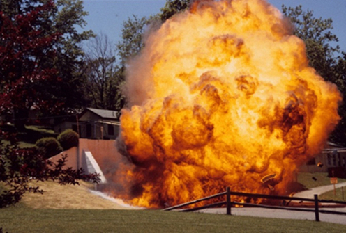
If you were standing downstream of a mine explosion, you would see the flame front approaching at a speed in excess of 1200 ft./sec. You can see the effect of the shock wave out in front of the flame front.

Often, these explosions will ultimately vent to the outside. Here is one such event – a research experiment, not an operating mine explosion, at the U.S. Bureau of Mines’ experimental mine near Pittsburgh. Much of what is known about these explosions and their prevention was developed by researchers at this facility.
Fortunately, these explosions are rare in the U.S. The last coal dust explosion occurred in 2010. You have to go back four decades to find the one before that (actually there were a few smaller gas explosions during that period as well). Unfortunately, they have not been eliminated.
So, what more can we do to prevent these horrible events? Hopefully, this more detailed explanation of explosions has given you an idea or two! What do you think?
First off, we need to clean up accumulations of float dust. In fact, the law requires such cleanup to occur, and you will be fined if an inspector finds excessive accumulation of float dust. This is a very important “housekeeping” function. While you can successfully cleanup float dust accumulations near belt drives and along the belt line, it is impossible to prevent fine layers of dust from accumulated on the mine ribs and floor. Consequently, we need another approach, and that is the application of rock dust, which is known as rock dusting. We apply rock dust with rock dusters. I admit these terms are not very imaginative, but at least they will be easy to remember!
What is this rock dust and why is it effective? Rock dust is usually limestone that has been crushed to a fine powder. When we rock dust, we are applying, and literally blowing, this powder onto every surface in the coal mine. What purpose does this serve? Well, first off, this dust is inert, i.e., it is not combustible. Let’s assume that we’ve applied rock dust to all surfaces, and with this practice in place, let’s revisit the propagation of the explosion.
As explained previously, the shock wave moving ahead of the flame front disperses any dust into the air, and then the flame front ignites the dispersed dust cloud, and the explosion continues to propagate. But, what if the dispersed dust were an inert material like rock dust? Two good things would happen. First, the explosion would be deprived of new fuel, and second, the mass of the rock dust will reduce the temperature of the flame front. The net effect is that the explosion is quenched. Thus rock dusting can prevent dust explosions; but only if it is applied in sufficient quantity. Based on NIOSH research, MSHA regulations require that sufficient rock dust be applied so that the resulting mix of float dust and rock dust contains a minimum of 80% of inert, i.e., incombustible, content. Rock dusting is an essential and critical auxiliary operation in coal mining, and the law requires that all areas within 40’ of the active mining face be rock dusted.
You may be interested to know that you cannot use just any rock dust for this purpose. The law defines the specification for rock dust as follows:
Pulverized limestone, dolomite, gypsum, anhydrite, shale, adobe, or other inert material, preferably light colored, 100 percent of which will pass through a sieve having 20 meshes per linear inch and 70 percent or more of which will pass through a sieve having 200 meshes per linear inch; the particles of which when wetted and dried will not cohere to form a cake which will not be dispersed into separate particles by a light blast of air; and which does not contain more than 5 percent combustible matter or more than a total of 4 percent free and combined silica (SiO2), or, where the Secretary finds that such silica concentrations are not available, which does not contain more than 5 percent of free and combined silica.
I am not going to test you on the specific details of this definition, but I thought that you might be interested to know the standard.
Rock dusters come in a variety of shapes and sizes, but consist of a storage vessel for the bulk rock dust, a feeder, and a compressed air system to entrain the rock dust in an air stream. Application can be through hoses directed by a miner or broadcast in all directions around the rock duster. In some instances, it is desirable to apply rock dust continuously, and in those cases, trickle dusters dispense a small but continuous stream of rock dust into the air stream. This is done, for example, in certain return aircourses and belt entries.
One of the most surprising sights to people going into a coal mine for the first time is that the mine is white rather than black! Rock dusting is the reason for that!
It’s tough to find a really good video illustrating rock dusting. This one here (2:53) does a reasonably good job at the 2-minute mark; and the other operations that you can see in this clip are worthwhile watching as well.
Ok, let’s continue with our study of unsupported mining methods!
9.3.2: Shrinkage Stoping
9.3.2: Shrinkage Stoping
Shrinkage stoping is a vertical stoping method, conducted in a vertical or near-vertical plane, and at an angle greater than the angle of repose of the broken ore. A defining characteristic of shrinkage stoping is that most of the blasted (broken) ore remains in the stope to support the hanging wall and footwall. However, when ore is broken, for example by blasting, it swells, i.e., its volume increases. This swell may be as much as 30% or even more. Therefore, as mining progresses within the stope, it is necessary to draw off some of the broken ore – to make room for the next round of drilling and blasting as well as to create space for the next slice of ore to be blasted into. This drawing off was known as shrinking, and hence the name associated with this method: shrinkage stoping.
Let’s take a closer look, using the following figure.
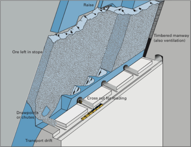
Although not shown, a shaft has been sunk on the footwall side of the deposit, and among other development workings a haulage drift has been driven, and then crosscuts into the orebody. Next, draw points and chutes were constructed by drilling and blasting in exact patterns. Then, the orebody within this stope is undercut. Raises are constructed at each end of the stope to provide manways for personnel access (ladders) as well as to provide ventilation and utilities, such as compressed air lines. This is a very labor-intensive method.
As an overhand stoping method, holes are drilled, loaded, and shot. A portion of the broken ore is drawn off to create sufficient space to allow the drilling and blasting operations in the stope. Once the newly drilled holes are drilled and loaded, the miners and equipment will be withdrawn. At that time, an additional portion of ore will be withdrawn to create sufficient space to account for the swell of the ore that will be blasted. Once this has been done, the round will be fired. Then a portion of the ore will be withdrawn to create space for the overhand stoping to continue. However, before the drillers re-enter the stope, any required ground control will be taken care of. Given that the ores are usually strong, little ground control will be required, other than scaling any loose materials. After it is safe to re-enter the stope, the cycle will repeat.
All right, let’s fill in some additional detail. First of all, why are we leaving ore in place? Essentially, to keep the hanging wall and footwall from closing open stope, and causing a failure. Typically, the ore is strong, but the country rock, less so. This method works well with narrow veins, as thin as 3’ or thicker veins of 100’ or so. Stope lengths vary from 150’ to 300’ and heights of 200’ to 300’. In narrow veins, the stopes are laid out longitudinally, whereas in thicker veins they will be transverse. The key design parameters in shrinkage stoping are the dimensions of the stope, largely governed by the size and shape of the deposit. Although rock mechanics will enter the picture in determining the size of the stope, the openings used are generally relatively small and are not excessively stressed. Therefore, the major concern is to maintain a manageable-sized stope that ensures a smooth flow of ore by gravity and effective draw control.
A high-quality ore, i.e., high grade and a valuable commodity, is necessary given the high cost of this method. It is labor intensive, and productivity is low compared to other methods. Furthermore, the ore needs to be uniform in quality, as the method doesn’t lend itself well to blending. There are a few other characteristics of the ore that are important. When blasted, the ore should not pack – if it does, you won’t be able to draw it off, and secondary blasting may be required. The ore may remain in the stope for six months to a year, and during that period it should not oxidize, as oxidation can create mineral processing problems, or worse, spontaneous combustion can occur, creating a carbon monoxide and fire hazard.
This method in its original form, as described here is, is unlikely to be used anymore. The last mine that I am aware of in the U.S. was a platinum/palladium mine in Montana. Despite the advantages of this method, it has two really serious disadvantages: one is safety and the other is productivity. Miners working in the stope after each blast presents a level of risk to their safety that cannot be justified by modern standard. From a productivity perspective, there are multiple problems. It requires the use of small equipment and multiple miners. The working surface for the miners is the blasted ore, which makes it difficult to move equipment. Given these serious limitations of the method, you should be asking yourself the question: why are we bothering to talk about this method? As it turns out, there is a modern variation of this method, which is quite successful, and accordingly, quite popular. The variant is known as the vertical crater retreat (VCR) mining method. It was invented by mining engineers working in the nickel mines in Canada. The company, INCO or International Nickel Company as it was known, obtained a patent on the method, and until the patent expired near the end of the 20th century, INCO had exclusive use of this new method.
Vertical Crater Retreat (VCR)
As a variation of shrinkage stoping most of what we said there, applies here, except for the differences that I am going to point out to you now. VCR is much safer because miners and equipment do not enter the stope, and VCR is amenable to a high level of mechanization. In these two differences, VCR has overcome the two primary disadvantages of shrinkage stoping that we identified. This is all well and good, but how does VCR achieve these two improvements? Let’s take a look at the following figure.
Before going into any detail, I should tell the underlying secret that made VCR possible: significant advancements in drilling technology, and specifically down-the-hole drills. You’ll see why this is so important in a moment.
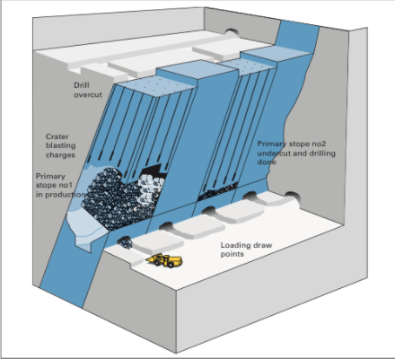
The initial development of the stope for VCR is the same as for a shrinkage stope. The one addition is the need for an overcut at the top of the stope, for that is where all of the drilling and blasting will originate. Either from the shaft or a ramp, crosscuts will be driven over to the overcut level. The overcut will be mined out, and then this will serve as the location where the miners will work. Rather than being in the stope with the attendant hazards, the miners are on top of the stope working from a stable and safe location.
From the overcut, they will use down-the-hole drills to drill the full length of all of the holes that will be required to mine the stope. Drilling holes of that length, accurately, is difficult. If the position of the holes varies by more than a few percent, the rock fragmentation will suffer. Oversize material will result, and will likely cause serious problems when they try to draw down or shrink the stope. Excessive fines will be produced, and they will likely cause plugging and packing. As such, very accurate drilling technology must be used. That’s where the advances in DTH enable the success of VCR. Of course, DTH is only an enabler. It also took clever innovation in the blasting design, and specifically in the development and refinement of crater blasting.
The drilling pattern is a grid on the order of 12’ x 12’. The hole diameters are on the order of 6”. While there is engineering guidance in the literature for the design of these crater blast rounds, many of the best practices are closely guarded secrets within the companies using this method.
Once the holes have been drilled, the lowest part of each drill hole is charged with explosive. The explosive is detonated, and a portion of the fragmented rock is drawn off to make room for the next blast. The lowest part of the holes is again charged, the blast is set off, and the cycle repeats. Usually the blast would be designed to take off a 10’ slice of ore. The design and execution of the spherical charges is technically challenging, and there is significant art as well as science to a successful application of crater blasting.
As with shrinkage stoping, there is some revenue from the ore that is drawn off during the development of the stope, but the real “payday” comes after the stope has been completely fragmented. Then the broken ore can be drawn off and sent to the mill over a period of several months.
9.3.3: Sublevel (Open) Stoping
9.3.3: Sublevel (Open) Stoping
If we had a stronger and more competent host rock, we could dispense with the need to keep ore in the stope to support the hanging wall, as we do VCR mining. Indeed, such deposits do exist, and when they do, we can employ the open stoping method. There are different variations, but essentially, we delineate stopes, and then through drilling and blasting, we slice off segments of the ore, and remove the blasted ore through draw points. We often divide the stope vertically by driving sublevels longitudinally, and then we ring drill with the sublevel, charge the holes, and initiate the blast. The progression of the sublevel blasting is coordinated spatially from sublevel to sublevel, so that the blasted ore from a sublevel is free to fall to the bottom of the stope where it will be drawn off.

The vertical spacing between sublevels is limited by the accuracy of the ring drills. As with the innovation of VCR, the accuracy of DTH drilling technology led to a variant of sublevel stoping known as big hole stoping. As you can see in the following figure, the ring drilling has been replaced with long-hole drilling. Using DTH drilling the vertical spacing can be increased significantly, and this means less time and cost to develop the sublevels. The holes are typically on the order of 300’ in length and approximately 6” in diameter. A slice of approximately 10 to 15’ is blasted with each round. Ultimately the size of the blast is limited by concerns of blast damage, and as increasing amounts of explosive are detonated, the risk of damage increases.

You can also notice in this drawing the vast open spaces created as the stope is mined out. As you recall, a condition for using open stoping is that the host rock be reasonably strong. Here, you can see why this is the case.
In our discussion of shrinkage and open stoping, including the variations of these two major methods, I didn’t say anything about pillars used to separate stopes. There will be a pillar remaining over the entire stope, and this is known as a crown pillar. The pillar underlying the stope is the sill pillar. Finally, there will be pillars separating the stopes transversely, which do not have a special name. Often, there is significant ore of considerable value contained in these pillars. Mining these pillars, however, presents a major challenge: if you attempt to take out the pillar, everything is likely to cave in. It’s rather difficult to recover the ore, if the entire mine in that area has collapsed!
Well, mining engineers are clever, and they have devised means of safely recovering the economic value remaining in the pillars. That’s an interesting story and one that we will tell in the next lesson when we look at cut and fill mining. Stay tuned!
Before moving on to the supported methods, let’s identify some of the equipment commonly found in these different stoping operations.
| Stoping Methods |
|---|
| Jumbo drill |
| Ring drill |
| Down-the-hole drill |
| LHD |
| Mine truck |
| Bolter |
| Powder loader |