Lesson 9.4: Supported and Caving Methods
Lesson 9.4: Supported and Caving Methods
We examined the unsupported class of methods in the last lesson and saw that this class is by far the most prevalent, i.e., those methods account for the vast majority of all mines. Nonetheless, the supported and caving classes are important in those circumstances that match these methods. Let’s examine each class in more detail.
9.4.1 The Supported Class of Mining Methods
9.4.1 The Supported Class of Mining Methods
Supported methods are those that require significant artificial support to maintain stability in the exploitation openings of the mine. We like to use pillars of the original rock mass as the ultimate form of ground control in an underground mine, because they are capable of providing near-rigid support. However, some orebodies are too weak to employ pillars for support. Often, the host rock is not very strong. Pillars are not an option, as a primary means of support, and consequently attempts to remove the ore will likely result in structural failure of the opening. It may not occur immediately, but over the time period that the opening would be needed, failure is likely to occur. Thus, the supported methods are used when production openings will not remain standing during their life. Support methods are also used when surface subsidence cannot be tolerated.
Whoa, but wait a minute. Didn’t we say that caving methods are applicable when the rock caves readily? Ok, then why would we use a supported method, rather than a caving method, for these weak orebodies? Good question, for which there are two good answers! One is that caving to the surface will cause a subsidence zone, i.e., the surface will literally collapse and sink by an amount close to the thickness of material removed in the mine. If you are in the middle of “nowhere,” it doesn’t matter. If there are bodies of water, e.g., rivers and lakes, or towns, for example, you will not want to subside them! The second answer to the question is that supported methods can be extremely selective, whereas caving methods are just the opposite.
We could say that the supported class is employed when the other two classes of methods, i.e., unsupported and caving, are not applicable.
The supported class of methods is intended for application to rock ranging in competency from moderate to incompetent, and includes:
- Cut-and-fill-stoping
- Stull stoping
- Square-set stoping
Cut-and-fill and stull stoping is applicable to moderately competent rock, and square-setting is for the least competent rock. Mechanization requirements and labor costs have all but eliminated stull stoping and square-set stoping. Nonetheless, I’ll briefly explain them because it may give you some ideas if you ever want to recover a very small part of the deposit and no other approach is possible.
9.4.1a Cut and Fill Stoping
9.4.1a Cut and Fill Stoping
Cut and fill is a very expensive method, but is very selective. You might predict the type of deposits in which it would be employed as the principal mining method. High value metalliferous ores such as gold or silver are often mined by this, and when the high-grade ore is in veins, the high degree of selectivity of this method is a real asset.
The basic concept of cut and fill is straight forward: we mine a portion of the stope, and then we completely backfill the mined portion. The backfill may simply be broken rock, but more likely is a mix of cement and waste rock. This backfill serves to support the stresses that were originally borne by the ore, and we’ll talk more about the backfill material in a while. Deciding how much ore to recover before beginning the backfilling is an important engineering decision. If you take too much or leave the opening unsupported for too long, it will fail. If you error on the conservative side, your productivity will suffer, and the mining cost will escalate.
So, let’s take a look at one implementation of the cut and fill method. We define a stope by driving an upper and lower haulage level. This defines the height of the stope, and a height of 150’-300’ is typical. The length of the stope is running left to right in the figure below, and may be on the order of 200’-2000’. The width of the stope is going into the page, and in this drawing you cannot tell anything about the width. The width would need to be at least 6’ and may be as much as 100’.
What determines these dimensions? First, you will try to keep your stope within the mineralized zone of the orebody. Second, ground control considerations will prevent you from making the stope too large. Third, the equipment that you are using will require certain minimum dimensions. If the equipment is 8’ wide, then the narrowest dimension of the stope, which is the width, must be greater than 8’.
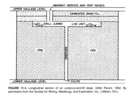
Looking at the figure, you can see the progression of mining activity. This figure is representing an undercut and fill cycle. Drifting or breast stoping is started with the jumbo drill. The holes are charged and shot, and then the LHD loads out or mucks the broken ore, and drops it down the orepass. The orepass is a raise that has been excavated for that purpose, and typically the raise will be protected with a grizzly at the top. This is done to prevent a large rock from plugging the orepass. If that happens, it is very dangerous. Someone has to go down into the orepass to drill and blast the plug. Anyway, as soon as we’ve completed mining the slice of ore, we will begin to backfill. The height of the slice that we take will be determined by ground control considerations, and is likely to be at least 10’ but no more than 30’. The ore will be collected at the lower haulage level and taken out of the mine. It is likely that mine trucks will be used, and there may or may not be a hoist involved in the operation.
Ok, now that you have the basic concept, there are a few variations. The figure illustrates mining moving downward, which we know as underhand stoping, and, in this case, we modified the term cut and fill to undercut and fill. In some deposits, we may choose to mine the orebody in an upward direction, which we know as overhand stoping. In this case, we modified the term cut and fill to overhand cut and fill. Finally, there are times when we progress in small slices, with an ultimate direction of up or down in the deposit; but, in this case, we often call it drift and fill. Don’t stress over the nuances of these terms, but you should already know what we mean by: overhand, underhand, and breast stoping; undercut and fill; and overhand cut and fill.
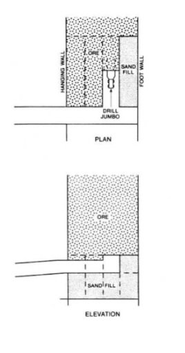
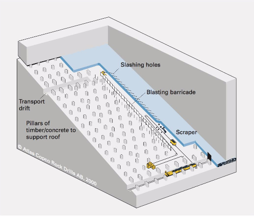
Here, below, is a deposit in which the ore is so weak that we cannot take a slice across the entire length of the stope, and have to take it in small slices – backfilling each as we go. This is an example of a drift and fill operation.
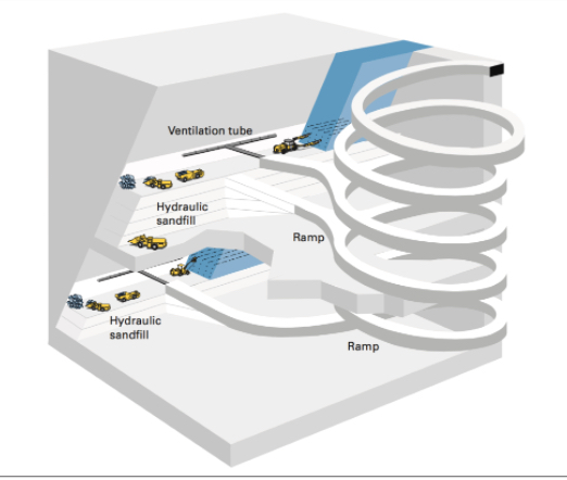
Next, we have a diagram of a modern cut and fill operation with a ramp in place. If you were to go into the underground gold mines in Nevada, for example, you would see mines similar to this. This particular example is using overhand cut and fill, but you will also see undercut and fill in practice there.
Fill and Backfilling
Significant research has gone into the development of fill materials, the engineering practices to use backfill, and the design of cut and fill mines. Let’s take a closer look at the fill.
Historically, waste rock mined underground, tailings from the prep plant, or rock quarried from a nearby location on the surface were used as backfill. In the former two instances, backfilling serves a secondary purpose of disposing of useless byproducts. Rather than accumulate large mountains of tailings on the surface near the mineral processing plant, we can use them productively in the active mine. Over the years, the practice of adding cement to these raw materials was incorporated into most operations. The addition of cement allows for a stronger backfill to be formulated and placed. It also can be used to provide a smooth working surface. If you are overhand stoping, for example, your equipment will be working from the last backfilled surface. By adding extra cement to this top layer, the equipment and miners will work more productively and safely.
Engineers generally consider three types of fill
- Hydraulic fill: tailings (55 - 70% solids) and 3-4% cement, with a 10% cement mix to top off the fill (smooth hard surface). Pumped underground as a slurry.
- Paste fill: unclassified tailings (up to 88% solids) with only a few percent cement. Requires precise mix and a more expensive plant but offers a stronger backfill and the use (recycling) of a higher percentage of tailings.
- Cemented rock fill: originally waste rock was used to fill the stope, and then hydraulic fill was sprayed on top to form the working surface. Today, the cement is often added at the surface, and then the backfill is dropped down a winze.
You don’t have to memorize these three types, but I’d like you to have an approximate idea of the mix for hydraulic fill.
Here, below is a photo of a paste fill plant, where the tailings are dewatered and mixed with the cement, and then pumped into the mine for placement.
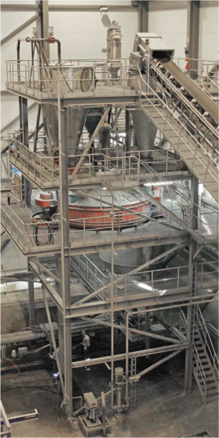
It is important to note that backfill can represent 10 - 20% of the mining cost, and of that cost, nearly 75% is the cost of the cement!
Cut and fill is an important mining method because it enables the recovery of high-value metal deposits in weak rock. The ability to be very selective with this further enhances its usefulness in many of these deposits, in which the spatial characteristics of the deposit require a more selective method. There is another important use of the method, and that is in pillar recovery.
I did mention earlier that often there is a significant value in the pillars that remain after the stope has been mined. In shrinkage stoping or open stoping, the crown and sill pillars as well as the pillars separating the production stopes contain significant ore. But how do you safely recover them? They are there to support the mine openings, and if you attempt to remove them, the openings will collapse. The solution is to backfill the mined-out area around the pillars. Then, with the backfill supporting the weight of the overlying rock, you can safely extract the pillars. Of course, the economics of doing so must be analyzed carefully.
This method of pillar recovery is also practiced in some metal mines employing the room and pillar method. A notable example is in the Viburnum Trend in Missouri – a famous lead-zinc mining region in the U.S. There they have roughly one million dollars of ore tied up in one pillar. Using a cut and fill approach, which is expensive, they are able to recover the pillars profitably.
9.4.1b Square Set Stoping
9.4.1b Square Set Stoping
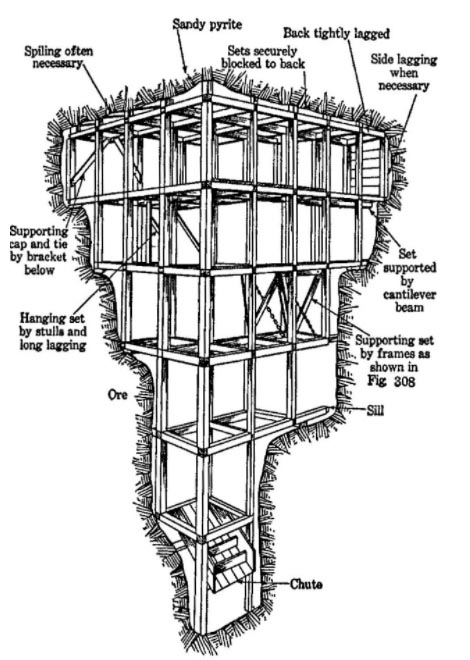
This mining method was used to mine in the weakest of rock masses. It is extremely expensive, and you’ll see why in a moment, but was used to recover silver and gold deposits through the 1970s in the U.S. The concept of the method is simple: we will mine only a small volume and immediately build and place timbers into the opening to support it on all sides. The timbers will be precisely cut and fitted to form a cuboid. This process will continue indefinitely, resulting in mines with thousands of these square sets. The dimensions of the square set will vary, but 6’x6’x8’ would be illustrative. Take a look at this figure, which illustrates a small portion of a mine with the square sets. The timbers are large, at least 6” square and likely between 8”- 12” or larger. The cost of acquiring such timbers today would be cost prohibitive, but that cost would be small compared to the labor cost to build these square sets. Elaborate and precise joinery was required so that the strength of the square set as not compromised. Today, it is difficult to find carpenters with the skill to construct such precise joints! Note in the figure the use of the lagging to keep the weak ground from flowing into the area supported by the square sets.
9.4.1c Stull Stoping
9.4.1c Stull Stoping
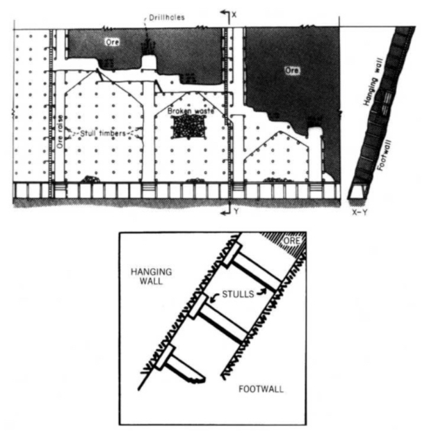
This method is designed for rock masses that are weak but somewhat competent – not as weak to require square sets, but not sufficiently competent to use cut and fill. The method is also conceptually simple. Place timber posts at close intervals to maintain the opening between the hanging wall and footwall. A serious shortcoming of this method is that the close placement of the stulls effectively prevents the use of mechanized equipment. Hand drilling with stoppers, drifters, or sinkers is required; and load is accomplished with labor-intensive approaches such as slushers, small overshot loaders, and so on. Needless to say, as a principal mining method, this one has also disappeared.
However, with this observation, I want you to consider that you could apply this approach to a very small area of a mine, where you had a unique challenge; and it could be a safe and economic solution to whatever your problem is. Instead of timbers, you might use hydraulic jacks. Regardless, there is value in having an awareness of these older but now obsolete mining methods. This reminds me of another very important point. Just because you select a particular mining method, and then successfully use it for a period of time… don’t think you are required to continue using that method if the conditions are changing. As a mining engineer equipped with knowledge of these methods, do not be afraid to change methods if the conditions warrant, or even to modify a method to suit your needs. The need for this, and the opportunity to do so, is most likely to occur in metal deposits.
9.4.2 Caving Methods
9.4.2 Caving Methods
So far, we have studied mining methods that require exploitation workings to be held open, essentially intact, for the duration of mining. Specifically,
- if the ore and rock are sufficiently competent, unsupported methods are adequate;
- if ore and rock are incompetent to moderately competent, then supported methods must be used.
We will now study a class of methods in which the exploitation openings are designed to collapse; that is, caving of the ore or rock or both is intentional and is the very essence of the method.
We define caving methods as those associated with induced, controlled, massive caving of the ore body, the overlying rock, or both, concurrent with and essential to the conduct of mining.
There are three current methods that are considered to be caving methods:
- Block caving
- Sublevel caving
- Longwall mining
Sublevel caving and block caving have application to inclined or vertical, massive deposits, almost exclusively metallic or nonmetallic.
Longwall mining is used in relatively flat-lying and tabular deposits such as coal, primarily, but the method is used to exploit some noncoal minerals, such as trona.
Longwall mining is a moderately priced method, and sublevel and block caving are among the cheapest of all the underground methods.
The caving class is truly unique because the exploitation openings are deliberately destroyed in the process of mining. Now, having said that, I suppose that before we go any further with this discussion of the caving methods, I should clarify one point. Do not think, even for one second, that because caving is the desired outcome, you are relieved of your engineering obligations for ground control! It is as important to apply rock mechanics to ensure that caving will occur as it is to prevent the occurrence of caving! In effect, the cross-sectional shape of the undercut area (i.e., the width-to-height ratio) must be sufficiently elongated to cause failure of the roof or back. Further, the development openings must be designed and located to withstand shifting and caving ground, as well as subsidence that usually extends to the surface. Thus, there is no shortage of significant ground control challenges with the caving methods. And it doesn’t stop with the engineering. In caving operations, the rate of production may be more important than in many other methods. Specifically, production must be maintained at a steady and continuous pace to avoid disruptions or hang-ups in the caving action.
Let’s take a look at each of the three methods in this class.
9.4.2a Block Caving
9.4.2a Block Caving
This method, which was developed in the U.S. after WW I, is well suited for mining in weak orebodies. Panels or blocks of ore are undercut. Once undercut, the weak orebody begins to cave under its own weight. The caved ore is drawn off through draw points. As the ore is drawn off, the orebody will continue to cave under its own weight. This process will continue until all of the orebody within the block or panel has been recovered.
Under proper conditions, this underground method can rival economically surface mining! It can do so because it is a bulk or high-volume mining method. But it is not a selective method. In the caving and drawing process, you take everything; and therefore this is not a viable method for following rich mineralized zones, for example. If you were in weak ground, and you wanted to follow mineralized zones, which method would you first consider? Cut and fill? Yes! The method works well for low-grade ores where you have to mine large quantities cheaply to be profitable. Examples include low-grade copper and molybdenum deposits, diamond-bearing Kimberlite pipes, and certain iron ore deposits, among a few others.
Given the foregoing discussion, let’s summarize the conditions that we expect to see for a successful application of block caving.
- Massive orebody (both horizontally and vertically)
- Low grade ore (the method is not selective)
- Orebody must cave easily into manageable pieces
- block - largest cave volume, weakest ores
- panel - intermediate volume, weaker ores
- mass - smaller volume, weak ores
- The host rock, i.e., the hanging wall has to fracture and collapse, following the cave.
- Subsidence of the ground surface above the orebody has to be acceptable.
Note the breakdown of the orebody into the categories of blocks, panels, and masses. These relate to the size of the cave area. If the ore is very, very weak you can have a wide stope. On the other hand, if you try to have a wide stop with a moderately weak ore, you are likely to get bridging within the stope. Caving stops at that point, and it develops into a very dangerous as well as production-killing situation. Thus, the cave volume has to be reduced as the ore becomes marginally stronger. In some mines, they will talk about their panels, and in others, their blocks. Now, you know the reason for this difference in the words they use.
Let’s take a look at a video of block caving before going on. This video will give you a good understanding of the method. There are some other details of note as well:
- Decline and shaft, and the purpose of each
- Ground control measures
- Drawbells
- Undercut level
- Ring drilling
- Materials handling
- LHDs
- Crusher - Orepass
- Conveyor Belt
- Ore skips (hoist)
- Subsidence zone
- Automation
Please watch the following video (3:44) entitled "Block Caving"
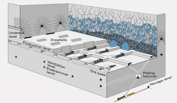
Here, below, is a view of a block caving operation, which depicts the information that you saw in the video, but in a slightly different form.
We can summarize what we learned from the video into the following steps for development and exploitation.
Development - Tasks
Development to prepare blocks for production caving is extensive and can take up to several years of advance work. On a per unit cost basis, the development for block caving is no greater than for sublevel caving.
- Sink Shaft and develop decline for access to the orebody from the footwall.
- Drive multiple headings to prepare haulage ways, crosscuts to develop undercut and draw points. Drive other laterals as needed.
- Develop the draw points and ore passes
- Install extensive ground control technologies to stabilize development openings, e.g., shotcrete, cable bolts, steel sets, arches, and so on.
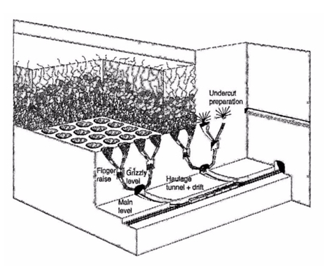
This figure, below, shows these development activities.
Exploitation - Unit Operations
- Drilling for the undercut using pneumatic- or hydraulic-powered percussion jumbos with a hole size 2 to 3 in.
- Blasting the undercut using ANFO or slurries; and bulk charging by pneumatic loader or pump with electric firing.
- Loading at the draw points with an LHD, or rarely today, a slusher.
- Hauling by LHD from the draw point to an ore pass, and then belt, rail, or truck to a hoist.
9.4.2b Sublevel Caving
9.4.2b Sublevel Caving
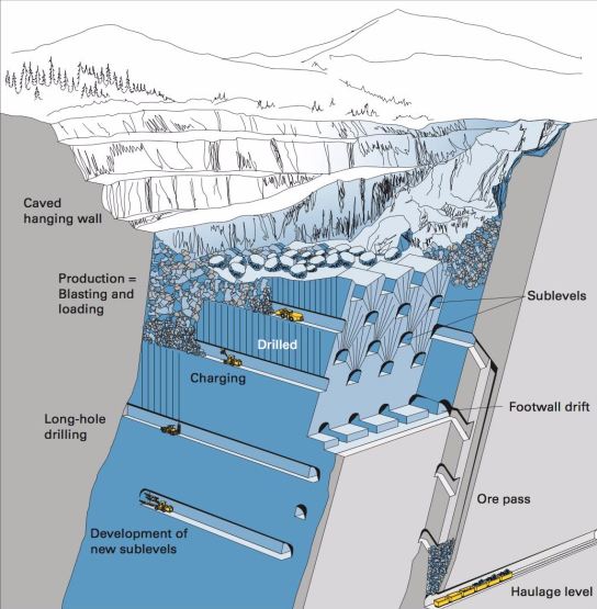
Sublevel caving shares many similarities with block caving, with one notable exception, which is responsible for this method: the orebody is competent and will not cave under its own weight. The host rock, on the other hand, is weak and caves behind the ore as it is extracted. Consequently, the orebody needs to be drilled and shot to extract the ore. Once extracted, the hanging wall caves. Given the similarities, we don’t need to say much, and especially if you look at this diagram of a sublevel caving operation, below. There are a few points to be made, however.
You will notice there is no need to develop and undercut, nor bells and drawpoints. Instead, a series of sublevels is developed, and next, the ore above the sublevel is fan or ring drilled. The holes are charged and fired. The broken ore is then loaded out of the sublevel using an LHD (or rarely, a slusher). The LHD’s travel to ore passes where the ore is dumped and then collected at a lower haulage level.
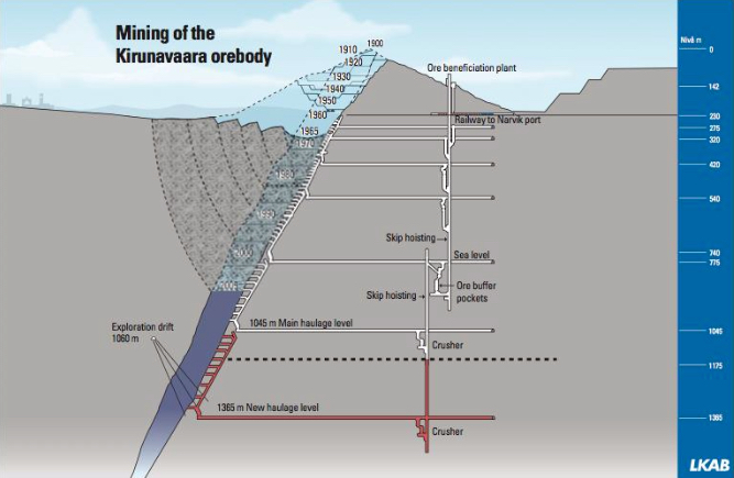
The world’s largest sublevel caving mine is located above the Arctic Circle in Sweden. The Kiruna Mine is mining the Kirunavaara iron orebody. (See figure below.) This mine is famous not only for its size and longevity, but it has been a hotbed of innovation for mining technologies over the years. I really like this figure because it tracks the mine’s development over the decades. You can see that the orebody was mined by open pit for nearly 50 years, and then they went underground. You can trace their progress over the ensuing 50 years up to the present.
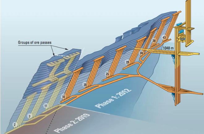
Looking at this next figure, you see the planned workings (sublevels) through 2019.
Block caving and sublevel caving require steeply dipping to nearly vertical deposits to enable the gravity flow of the rock. Longwall mining by contrast does not require this gravity flow of the caved material, and as such, it is well suited for tabular and nearly horizontal deposits.
9.4.2c Longwall Mining
9.4.2c Longwall Mining
Longwall mining applies to thin, bedded deposits, with uniform thickness and large horizontal extension. Typical deposits are coal seams, potash layers or conglomerates, trona, and gold reefs. Longwalls are found in nearly horizontal deposits of coal and trona, whereas in metal/nonmetal deposits, a steeper dip is tolerated. The difference is in the equipment that is used. Coal and trona are using massive suites of mechanized and semi-automated equipment that is unsuitable for use in greater than 5-10% grades. There are exceptions, but we’re not going to complicate this discussion with those.
Longwall mining takes its name from the characteristic long face or wall, which may be several hundred feet or more in length. The figure below illustrates this nicely. The ore is extracted in a slice along this long wall. The region adjacent to the face is kept open, i.e., free of obstructions, to allow space for miners and equipment. This region might extend 10’-20’ out from the wall. If we are looking at mining a gold reef, for example, a line of posts will be installed to support the roof or back and protect the active mining activity. At some distance back from the face, caving will be allowed to occur, and in most instances, this is necessary to relieve superimposed loads on the working face. If we are looking at a coal application, the process will be somewhat different. A significant percentage of the coal that is mined underground comes from longwall mines; and not just in the U.S. but around the world. As such, we’ll look more closely at longwall mining in coal.
Longwall Mining of Coal
Longwall mining of coal is a high production and high productivity method, employing sophisticated electrical, mechanical, and hydraulic systems, as well as computer-based monitoring and control systems. Most modern (coal) longwall faces are semi-automated. It is noteworthy that longwall operations in trona mines utilize essentially the same equipment and processes that are used in coal mine longwalls. As the long wall or face is mined and the roof supports advance forward with mining, the roof in the mined-out area will cave.
When the panel is initially mined, caving will be delayed. This is a worrisome period because all of the weight of the unsupported roof is transferred to the face and also the gateroad pillars. Sometimes caving may not start for 10 - 20 or more passes of the shearer. If the superimposed load becomes too great, the face and pillars can begin to crush. Thus, for longwall to work safely and productively, the cave must occur in a timely fashion. Once it has started to cave, it will generally continue with each pass of the shearer. Ground control experts will conduct a cavability analysis of the overburden before a decision is made to employ this mining method. This requirement for caving is the reason this method is classified in the caving class of methods.
Please be aware that the longwall panels within the coal deposit are created by room and pillar mining. Thus, many room and pillar (coal and trona) mines are also longwall mines, and in most of them, the room and pillar work is simply to develop the panels and the infrastructure to facilitate operation of the longwall. By that, I mean you need to have a well-developed ventilation, materials handling, and power systems to support a high production longwall. The room and pillar mining creates the mains, submains, and panel entries for these systems. Let’s look at a few figures. These won’t answer all of your questions right now, but these in combination with some videos that will come afterwards, should give you a good understanding of the method.
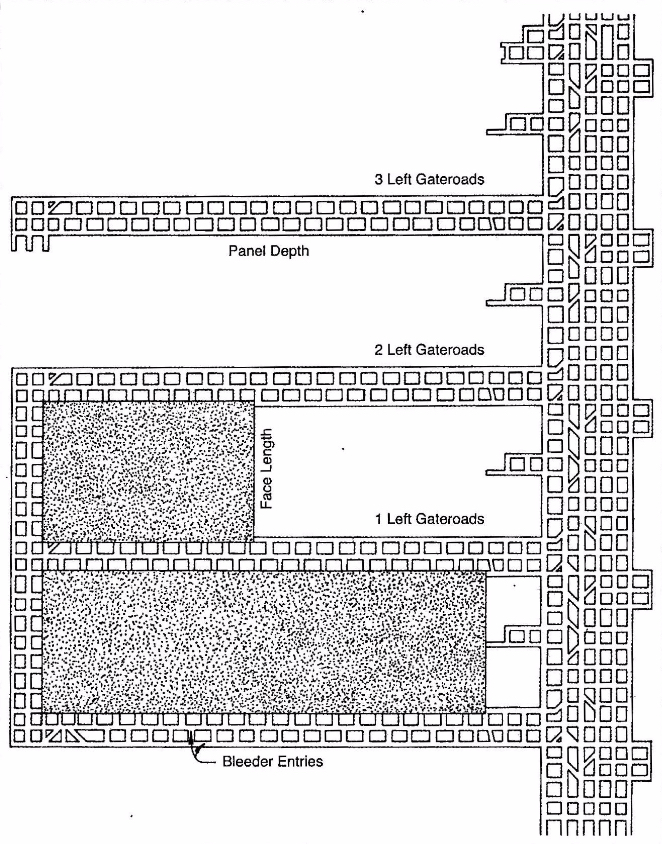
Let’s start with a plan view of a mine. This figure, below, shows a portion of the mains or submains and the longwall panels. Notice the three-entry gateroads that define the panels. One set of these will be known as the headgate entries and the other as the tailgate entries. The one of the longwall face will be known as the headgate and the other end of the face will be known as the tailgate. The entries adjacent to the mined out panel are the tailgate entries, and that defines the tailgate side of the panel. The longwall face is mined on retreat. That is to say, the gateroads are mined on advance, and then the longwall face retreats back to the submains or mains.
The equipment required for a longwall face is unique to this mining method. Let’s look at it in this figure below, and then when you see it in the videos, it will make more sense.
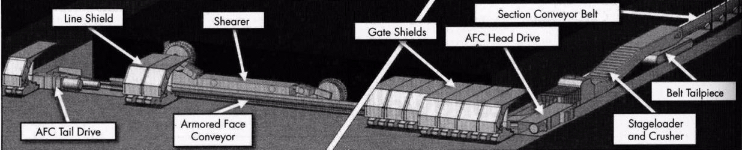
The armored face conveyor is a massive steel structure containing a chain conveyor. The shearer (or plow) rides on the AFC and cuts the coal. The cut coal falls into the AFC, and is transported to the headgate. At the headgate, the coal is crushed to a size suitable for transport on a conveyor belt and then fed at a controlled rate onto the belt. This panel belt feeds the outby belt system. It takes an enormous amount of power (1000s of hp) to operate the AFC, and there are drives at both the tail and headgates to power the chain conveyor. All of this equipment and the miners working at the face are protected by what has been called an umbrella of safety, i.e., the series of shields. As the coal is cut, the AFC snakes into place immediately adjacent to the face. On the right side of this figure, they are depicting this advance of the face, and you can see the shields that have moved into place.
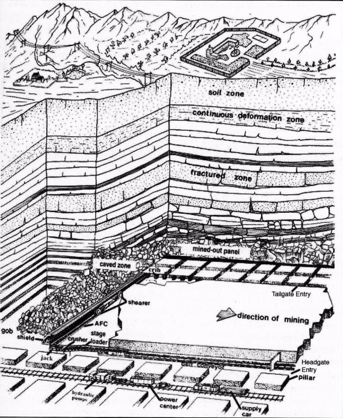
This next figure illustrates more completely the relationship of the longwall panel to the overburden, the gateroads, and the longwall face itself.
Next, let’s take a look at some videos, each of which is less than five minutes in length. I think these videos are helpful for the details that they show. There are four of them, and they are addressing the same basic topic. However, in each one you can see certain important details more clearly than in the other videos. I suggest that you watch all of them twice, and don’t hesitate to pause them and look more closely at the image. In so doing, you’ll develop a more complete understanding of the equipment and the process.
I want to make one correction to the videos. Caterpillar or CAT as it is known, is a global manufacturer of excellent mining equipment. One important detail of their second video is not quite correct, however. All longwalls in the U.S. use shearers, not plows, including the longwalls operating in thin seams. The reasons for this are not important here, but please remember that shearers, not plows are applied through the U.S coal fields. In MNG 410, we take a more detailed look at longwall mines, including the conditions that favor the use of the plow.
I imagine that you have a reasonable understanding of modern longwall mining after studying the figures and the videos. Allow me to summarize the process and add a few additional details of interest.
Development of the panels is done with the room and pillar method. It generally will take at least two continuous mining sections to develop the longwall panels. From a mine planning perspective, the goal is to ensure that you have panels developed and ready to go. Often, the mine will have spare longwall equipment, and they will partially set up a longwall face on the next panel, so that minimal time will be lost in moving to the next panel and commencing with longwall production. This requires that panel development activities stay far enough ahead of the longwalls to ensure that the next panel can be set up before mining of the previous panel is completed. However, it is important that panel development does not get too far ahead, which would result in developed panels sitting idle for several months. This would represent a poor use of resources, but more importantly, the roof rock often begins to deteriorate when exposed to the moist mine atmosphere. This could result in roof problems before you have begun to mine in those panels.
Services to the longwall face will be placed in the headgate entries. This includes the panel belt, the staged loader and crusher, the hydraulic pumps for the shields, the electrical power centers, the computer control boxes, and the refuge chamber.
The tailgate is under additional roof stresses, and requires additional roof support, such as concrete pillars, timbered crib structures, and so on.
The number of gate roads is typically three, which is a legal requirement in the U.S. Under severe ground pressures, fewer gate entries are advantageous. In the western U.S., a few mines have received special permission to have only two gate roads. Outside of the U.S., you will find single entry gate roads. A reduction in the number of gateroads does create safety hazards that must be managed.
Panel Development
- Develop the gate roads (headgate and tailgate).
- Connect the headgate and tailgate.
- Develop (mine) the setup rooms – the entries connecting the head and tail gate, are mined to specific dimensions and in a pattern to facilitate setting up the long face of equipment.
- Develop (mine) the recovery rooms – once the longwall has been mined, the longwall face of equipment must be moved to the next panel. Given the size of the equipment, additional openings are mined to facilitate the removal of the face equipment. Finish the setup of the equipment on the new panel.
Production Cycle
The basic production cycle is straightforward, as you no doubt saw in the videos. The cutter, whether a plow or shearer, mines along the width of the face. As the cutter moves, the shields advance forward. As they advance forward, the AFC is pushed to the face; and as such, it is ready for the next cut. A few details that are not apparent would include:
- Mining along the face can always be done in the same direction, e.g., headgate to tailgate, which is known as unidirectional cutting, or it can be done in both directions, known as bidirectional cutting.
- Beginning the cutting cycle at either gate is a multi-step process, requiring that the shearer cut into the gateroad, and then gradually cut into the face over a few hundred feet to reach its full cutting depth, returning back to the gate, and then commencing with a full web cut along the full face.
- The shields are lowered to move forward, and when in the new position, the canopy is extended. Usually, the shields will push into the roof momentarily to aid in the formation of a crack in the roof, which facilitates the caving action. The roof typically does not cave immediately after the shield advance, but once caving has begun, the roof will cave reasonably close behind the shields.
Closing Comments
Modern longwall mining systems represent the highest level of technology and engineering achievement in mining method design. The design of the individual components has pushed the envelope on electrical, mechanical, and hydraulic component design. The productivity of these systems is unrivaled, and the raw tonnages achievable per shift are staggering compared to what was state-of-the-art 20 years ago. As cutting technology advances to allow continuous cutting of harder materials, you will see these systems applied in other commodities… but only if what is true?
This brings us to the end of our discussion of the supported and caving classes of underground mining methods.