How Nuclear Energy Works
Maggie Koerth-Baker has a really great article on how nuclear power plants work, with a focus on the nuclear fission reaction and what mechanisms in a nuclear power plant keep the reaction from spinning out of control. It was written right after the incident at Fukushima Daichi. Before continuing on, please have a look at the article, and pay some attention not only to how plants work, but how the nuclear reactions inside the plants are controlled. The article also has a really nice description of how reactions at nuclear power plants can keep cascading even after the plant has been “shut down,” which is basically what causes meltdowns like those that happened in the Three Mile Island and Chernobyl power plants.
Activate Your Learning
As described in the article linked above, when a reactor core shuts down, it doesn't go all the way to zero immediately. It takes several days for the reactor to stop producing heat, which is typically what leads to meltdowns when they happen. Why isn't shutting down a reactor core like flipping a switch?
Click for the answer.
ANSWER: The control rods used to shut down a reactor core work by isolating the fuel rods from each other. This prevents new nuclear reactions from initiating. However, the control rods do not isolate or "shut down" individual uranium atoms within the same fuel rod, which means that reactions already in progress will continue until they have run their natural course.
The basics of a nuclear power plant aren’t actually all that complicated. In fact, there is a remarkable similarity to fossil fuel plants, in that what ultimately happens in a nuclear power plant is that steam is produced, to drive a turbine inside a generator, which produces electricity. But unlike fossil fuel plants, which heat water by burning fuel, the water in nuclear power plants is heated through an atomic reaction.
There are two basic types of atomic reactions. The first is nuclear fusion, with which we are all intimately familiar, whether we know it or not. It is nuclear fusion that keeps the sun hot. In nuclear fusion, atoms are joined together. The word “joined” here is a bit of scientific jargon. In reality, the energy is released when atoms collide together at really high speeds. If you have ever seen two cars collide at high speed, you have some idea of how energy could be released when things hit each other. Despite years of research into nuclear fusion, scientists have never been able to engineer a controllable reaction in a laboratory environment. If they could, most of the world’s energy problems would basically be solved overnight, since the amount of energy released through a fusion reaction would be massive. But for now, fusion goes in the “maybe someday” pile.
The second type of nuclear reaction is fission, which is the opposite of fusion – atoms are broken apart, which also releases energy. U-235 is naturally radioactive, meaning that the nucleus is unstable, and it will eventually give off some energy and parts of its nucleus to get to a stable atom, but this takes a long time — the half-life is 700 million years. The figure below illustrates roughly how this works. An atom (in the case of a nuclear power plant, a uranium-235 atom) is bombarded with neutrons, some of which are absorbed by the nucleus, so the U-235 becomes U-236 — this makes it even more unstable, so the atom splits apart into two lighter atoms called the daughter products. U-236 splits into krypton (Kr-92) and barium (Ba-141), and it also releases energy in the form of heat, gamma radiation (bad for us) and 3 neutrons. (Note that if you add up the weight of the daughter products and the neutrons, 92+141+3, you get 236, the weight of the U-236 that split apart). These neutrons come hurtling out of the original atom and smash into other uranium-235 atoms, triggering 3 more U-235 fission reactions, each of which generates 3 more neutrons. As you can see, before long, there are a lot of neutrons and thus a lot of reactions and thus a lot of heat, which heat the water surrounding the fuel rods, creating steam, spinning the turbine — just like many of the other systems for making electricity.
The nuclear fission reaction described above is an example of a positive feedback mechanism that will naturally tend to speed up until all of the fuel (the U-235) is used up. This means that it has a tendency to create more and more heat, and if left unchecked, this would cause the water in the reactor vessel to get too hot and build up too much pressure for the reactor to contain — then you would have a big steam explosion, such as happened at Chernobyl. To control this reaction, the reactor core has a series of control rods, made of materials that absorb the neutrons emitted during a fission reaction. So the control rods allow the operators to adjust the rate of the reaction and thus the rate of heat production.

Fission of 235-U is induced by bombardment of neutrons. The fission reaction produces heat, radiation, daughter products, and more neotrons that induce additional fission reactions.
Click for a text description of Induced Fission Reaction diagram
The image is a diagram illustrating the nuclear fission process of Uranium-235 (U-235) leading to the production of energy in the form of heat and radiation.
- Uranium-235 (235-U): At the top left, there is a yellow circle labeled "235-U," representing Uranium-235.
- Uranium-236 (236-U): An arrow from 235-U leads to an orange star-like shape labeled "236-U," indicating Uranium-236, which is an intermediate excited state formed when Uranium-235 absorbs a neutron.
- Fission Products: From 236-U, the diagram shows two main arrows splitting off:
- One arrow leads to a purple star labeled "92-Kr," representing Krypton-92.
- The other arrow leads to a blue star labeled "141-Ba," representing Barium-141.
- Heat and Radiation: Between the fission products, there is a large yellow starburst labeled "heat and radiation," indicating that the fission process releases energy in the form of heat and radiation.
- Additional Neutrons: Small blue circles at the ends of additional arrows coming from the heat and radiation starburst represent neutrons that are also produced during the fission process.
The diagram uses color coding and shapes to visually represent the transformation of Uranium-235 into Uranium-236, followed by its fission into Krypton-92 and Barium-141, along with the release of heat, radiation, and additional neutrons.
Source: David Bice

Pressurized Water Reactor.
Click for a text description of the Pressurized Water Reactor.
The image is a schematic diagram of a nuclear power plant, illustrating the main components and the flow of energy and fluids within the system. Here is a detailed description of each part:
- Containment Structure: The entire setup is enclosed within a large grey structure labeled "Containment Structure," which provides safety and containment for the nuclear reactions.
- Reactor Vessel: On the left side within the containment structure, there is a red and yellow structure labeled "Reactor Vessel." This is where nuclear fission occurs, generating heat.
- Control Rods: Inside the reactor vessel, there are grey rods labeled "Control Rods," which are used to control the rate of the nuclear reaction by absorbing neutrons.
- Pressurizer: Above the reactor vessel, there is a yellow component labeled "Pressurizer," which maintains the necessary pressure in the reactor coolant system to prevent boiling at operational temperatures.
- Steam Generator: Connected to the reactor vessel by red and blue pipes, there is a light blue structure labeled "Steam Generator." Here, heat from the reactor vessel is transferred to water in a secondary loop, turning it into steam.
- Turbine: To the right of the steam generator, there is a green component labeled "Turbine." The steam generated in the steam generator expands and spins this turbine, converting thermal energy into mechanical energy.
- Generator: Attached to the turbine, there is a grey cylindrical component labeled "Generator." The mechanical energy from the turbine is converted into electrical energy here.
- Condenser: Below the turbine, there is a blue structure labeled "Condenser," where the steam is cooled and condensed back into water after passing through the turbine.
- Flow of Fluids: The diagram shows the flow of water and steam with arrows:
- Red arrows indicate hot water or steam moving from the reactor vessel to the steam generator.
- Blue arrows show the flow of cooler water from the condenser back to the steam generator and reactor vessel
- City and Power Lines: In the background, there is a silhouette of a city skyline, indicating the end use of the generated electricity. Power lines extend from the generator to a power transmission tower, symbolizing the distribution of electricity to the city.
The diagram uses color coding to differentiate between hot and cold components (red for hot, blue for cold), and simple shapes to represent each part of the nuclear power plant's operation, showing the energy conversion process from nuclear to electrical energy.
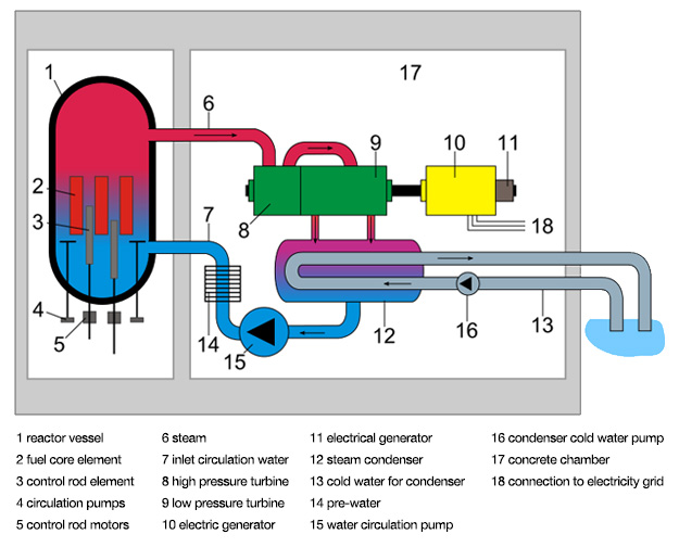
Boiling Water Reactor.
Click for a text description of the Boiling Water Reactor.
The image is a labeled diagram of a nuclear power plant, showing the main components and the flow of various fluids and electricity within the system. Here is a detailed description of each labeled part:
- Reactor Vessel - This is a large cylindrical container at the left side of the diagram, colored in red at the top and blue at the bottom, representing the containment vessel for the nuclear reaction.
- Fuel Assembly Element - Inside the reactor vessel, there are red vertical structures labeled as fuel assembly elements where the nuclear fission occurs.
- Control Rod Element - Also inside the reactor vessel, there are grey rods labeled as control rod elements, used to control the rate of the nuclear reaction.
- Circulation Pumps - At the bottom of the reactor vessel, there are small grey structures labeled as circulation pumps, which help circulate coolant within the reactor.
- Control Rod Motors - Below the circulation pumps, there are small grey components labeled as control rod motors, which move the control rods in and out of the reactor core.
- Steam - A red pipe labeled "steam" exits from the top of the reactor vessel, indicating the steam produced from the heat of the nuclear reaction.
- Inlet Circulation Water - A blue pipe labeled "inlet circulation water" enters the reactor vessel, representing the water that cools the reactor and turns into steam.
- High Pressure Turbine - The steam from the reactor vessel flows into a green component labeled as the high pressure turbine, where the steam's energy is converted into mechanical energy.
- Low Pressure Turbine - After the high pressure turbine, the steam moves into a larger purple component labeled as the low pressure turbine, continuing the conversion of steam energy into mechanical energy.
- Electric Generator - Connected to the turbines, there is a yellow component labeled "electric generator," which converts the mechanical energy from the turbines into electrical energy.
- Electrical Generator - Another electric generator is shown in yellow, connected to the low pressure turbine, indicating the generation of electricity.
- Steam Condenser - Below the turbines, there is a grey structure labeled "steam condenser," where the steam is cooled and condensed back into water.
- Cold Water - A blue pipe labeled "cold water" leads from the condenser to a body of water outside the plant, indicating the cooling water source.
- Pre-water for Condenser - A blue pipe labeled "pre-water for condenser" shows water being directed towards the condenser.
- Water Circulation Pump - Connected to the pre-water for condenser, there is a grey component labeled "water circulation pump," which helps circulate water through the condenser.
- Condenser Cold Water Pump - Another pump, labeled "condenser cold water pump," is shown in grey, which pumps cold water into the condenser.
- Concrete Chamber - The entire setup is housed within a large grey structure labeled "concrete chamber," providing containment and protection.
- Connection to Electricity Grid - On the right side, there is a grey line labeled "connection to electricity grid," showing where the generated electricity is sent out for distribution.
The diagram uses color coding (red for steam, blue for water, green and purple for turbines, yellow for generators, and grey for various structural and mechanical components) to illustrate the flow of steam, water, and electricity through the nuclear power plant's system. Arrows indicate the direction of flow for steam, water, and electricity.
There are two basic types of nuclear power plants that are in operation today. The first, and most common, is the Pressurized Water Reactor (PWR), which is illustrated in the animation below. In a PWR, hot water passes through the reactor core (where it absorbs the heat from the nuclear fission reactions) and is then pumped through a heat exchanger, where it heats another fluid that produces steam, powering the turbine. The primary advantage to this type of design is that the water in the primary loop (which passes through the core) does not actually come into contact with the fluid in the steam generator, so unless pipes or valves break there is no risk of contamination or radioactive water leaking from the plant. The Boiling Water Reactor (BWR), illustrated in the next figure, utilizes a somewhat simpler design, where the water that runs through the core is allowed to vaporize to steam, thus powering the turbine to generate electricity. While the design is simpler, it does mean that the steam entering the turbine can be radioactive.
Whether one design is inherently more advantageous than another is difficult to say. Both types have been involved in major nuclear power plant incidents. The reactor at Three Mile Island was a PWR while the reactor at Fukushima was a BWR, so the potential exists for problems at either type of plant. It is perhaps worth mentioning that the Three Mile Island incident was likely due as much to human error and poor design of the reactor’s control system at least as much as to the reactor design itself. The reactor at Chernobyl was an unusual Soviet design called a “light water graphite reactor” that was not really designed for use as a commercial nuclear power plant but was adapted for that use anyway. The World Nuclear Association(link is external) has a nice description of the Chernobyl plant technology with a description of what went wrong (here too, human error played a central role).
Advanced PWRs have been developed that use more passive designs to keep the reactor from overheating, without any pumps or offsite power required. Westinghouse has developed one such design, the AP1000, which is currently being deployed in China. For those who are interested, more information on passive PWR designs can be found at Westinghouse Nuclear(link is external).
