Conventional Hydroelectric Dams
There are three main types of conventional hydropower technologies: impoundment (dam), diversion, and pumped storage.
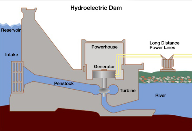
Impoundment is the most common type of hydroelectric power plant. An impoundment facility, typically a large hydropower system, uses a dam to store river water in a reservoir. Water released from the reservoir flows through a turbine, spinning it, which in turn activates a generator to produce electricity. Generation may be used fairly flexibly to meet baseload as well as peak load demands. The water may also be released either to meet changing electricity needs or to maintain a constant reservoir level. The layout of a typical impoundment hydropower facility is shown below in the first figure. One of the world’s most famous impoundment dams, the Hoover Dam, is shown in the second figure (although it’s worth noting that on a global scale, the Hoover Dam is more famous than it is large).
Conventional Impoundment Dam
Click for a text description of the Conventional Impoundment Dam diagram.
The image is a labeled diagram of a hydroelectric dam, illustrating how it generates electricity.
- Reservoir: At the top left of the diagram, there is a large body of water labeled as "Reservoir," which stores water at a higher elevation.
- Intake: On the left side of the dam, there is an opening labeled "Intake," where water from the reservoir is directed into the system.
- Penstock: From the intake, water flows through a large pipe called the "Penstock," which channels the water down towards the powerhouse. This pipe is shown running through the dam structure.
- Powerhouse: Inside the dam, there is a structure labeled "Powerhouse," where the main components for electricity generation are housed.
- Turbine: Within the powerhouse, there is a "Turbine" depicted. The water from the penstock is directed to spin this turbine.
- Generator: Above the turbine, there is a "Generator," which is connected to the turbine. The mechanical energy from the spinning turbine is converted into electrical energy by the generator.
- River: At the bottom right of the diagram, there is a body of water labeled "River," into which the water exits after passing through the turbine.
- Long Distance Power Lines: Extending from the powerhouse, there are lines labeled "Long Distance Power Lines," which carry the generated electricity away from the dam to distant locations. These lines are shown leading to a structure that looks like a power distribution station.
The diagram uses simple, clear lines and labels to show the flow of water from the reservoir through the intake and penstock, into the turbine within the powerhouse, and then out to the river. It also illustrates how the mechanical energy from the water's movement is converted into electrical energy by the generator, which is then transmitted via power lines.
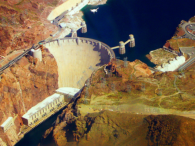
Hoover Dam
A diversion, sometimes called run-of-river, facility channels a portion of a river through a canal or penstock. It may not require the use of a dam but also has limited flexibility to follow peak variation in power demand. Thus, it will mainly be useful for baseload capacity. This scenario results in limited flooding and changes to river flow. In the United States, many of the dams in the Pacific Northwest (on the Columbia and Snake Rivers) are diversion or run-of-river dams, with limited or no storage reservoir behind the dam. The figure below shows a picture of a diversion hydropower facility. Compare what that facility looks like with the picture of Hoover Dam, the impoundment facility shown above.

Diversion or “run-of-river” dam
A “pumped storage” hydro dam combines a small storage reservoir with a system for cycling water back into the reservoir after it has been released through the turbine, thus “re-using” the same water to generate electricity at a later time. When the demand for electricity is low (typically at night), a pumped storage facility stores energy by pumping water from a lower reservoir to an upper reservoir. During periods of high electrical demand (typically during the day), the water is released back to the lower reservoir to generate electricity. The figure below shows a schematic of a pumped storage hydro facility. Pumped storage facilities are typically smaller in terms of generation capacity than their impoundment or diversion counterparts, but are sometimes combined with impoundment or diversion facilities to increase peak power output or flexibility.

Schematic of a pumped-storage hydro facility
Click for a text description of the pumped-storage hydro facility diagram.
The image is a cross-sectional diagram of a "Pumped-Storage Plant," illustrating the various components and the overall operation of the facility.
- Reservoir: At the top right of the diagram, there is a large body of water labeled "Reservoir," which is at a higher elevation.
- Intake: Water from the reservoir is directed into the system through an opening labeled "Intake."
- Switchyard: To the far right, above the reservoir, there is a structure labeled "Switchyard," which is involved in the distribution of electricity.
- Visitors Center: Near the top of the diagram, there is a building labeled "Visitors Center," located on the surface above the main infrastructure.
- Elevator: A vertical line labeled "Elevator" runs from the surface down to the underground sections, providing access between levels.
- Main Access Tunnel: A horizontal tunnel labeled "Main Access Tunnel" extends from the base of the elevator, leading to various underground chambers.
- Surge Chamber: Connected to the main access tunnel is a vertical structure labeled "Surge Chamber," which helps manage water pressure fluctuations.
- Powerplant Chamber: Below the surge chamber, there is a large room labeled "Powerplant Chamber," where the main machinery for generating electricity is housed.
- Breakers: Adjacent to the powerplant chamber, there is a section labeled "Breakers," which are electrical switches used to control, protect, and isolate electrical equipment.
- Transformer Vault: Below the breakers, there is another section labeled "Transformer Vault," where transformers are located to step up or step down voltage levels for efficient power transmission.
- Discharge: At the bottom left of the diagram, there is an area labeled "Discharge," where water exits after passing through the powerplant, flowing back into a lower body of water or river.
The diagram uses color coding (blue for water flow, brown for earth) and clear labels to show the path of water from the reservoir through the intake, down through the system, and how it's used to generate electricity in the powerplant chamber before being discharged. The various components are interconnected, illustrating the flow of water and electricity in a pumped-storage hydroelectric facility.
