8.5.4: Infrastructure Installation
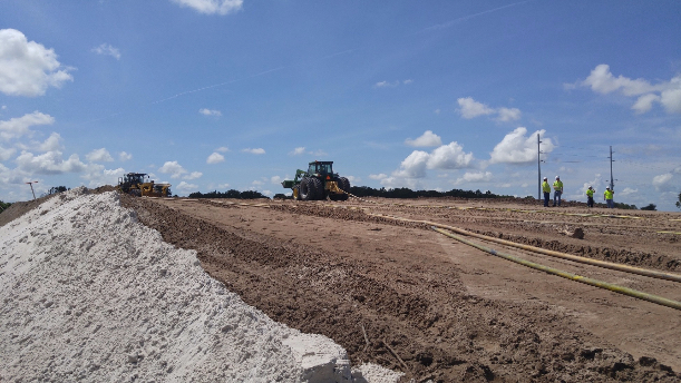
Once a level site has been prepared, the work of placing utilities will begin. In this photo, they are placing high voltage cable (yellow in color), which will supply power for the dragline as well as the many pumps used on the site.
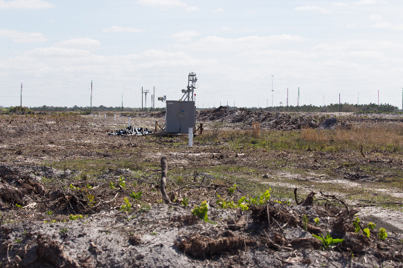
As work on the electrical power infrastructure is continuing, a series of dewatering holes will be developed. This photo shows the electrical infrastructure, and do note the overhead electrical lines in the background and the electrical installation in the foreground. If you look closely, you can see 6” diameter PVC pipes protruding at the surface of the ground. These are dewatering holes.
This next photo gives us a close-up view, and we can see other important features. There is a small pump at the bottom of this hole, and you can see the small discharge line, where the pumped water enters a larger diameter collection pipe that is serving the entire row of dewatering holes. You can also see the electrical cable that goes down the hole to the pump at the bottom. These holes go to the bottom of the matrix, and so, a typical hole would be 50 – 60’ deep. Those pretty pink flags that you see are markers so that equipment, such as tractors and pickup trucks, don’t accidentally run over and damage pipes or electrical cables.

This next picture focuses on an electrical installation. As is often the case, this equipment is mounted on a skid so that it can be attached by a wire rope to a dozer and pulled to a new location. This equipment provides the hardware to allow a connection to overhead power lines, if required, a transformer to step the voltage down to a level required by the machines and pumps, and protective devices to allow switching and implementation of other safety features.
