8.5.5: Overburden Removal
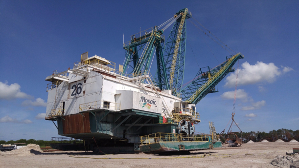
With the utilities in place, we are ready to install the pits and monitors and to begin overburden removal. Let’s talk first about overburden removal. A typical dragline in use at the Mosaic mines in Florida is shown in the next picture. Remember, we talked about how draglines move – they walk. Look at the two big walking shoes on this dragline, one on each side. The shoe is green and there is a yellow guardrail around the top surface of the shoe. As you might imagine, these things don’t break any land speed records!
Here is another aerial view of the mine, but in this one, you can clearly see the dragline at work.
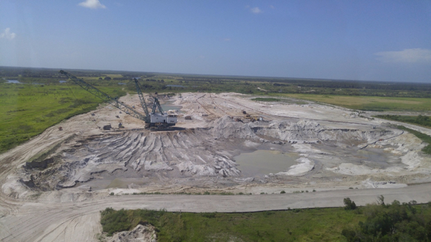
Here is a close-up of the dragline removing overburden. If you look to the left, you can see the last strip or cut that was mined (it is now filled with water).
This short video clip (2:11) will give you a feel for the overburden removal cycle. Note the development activities ongoing to the left of the active cut.
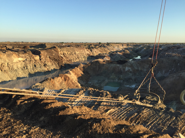
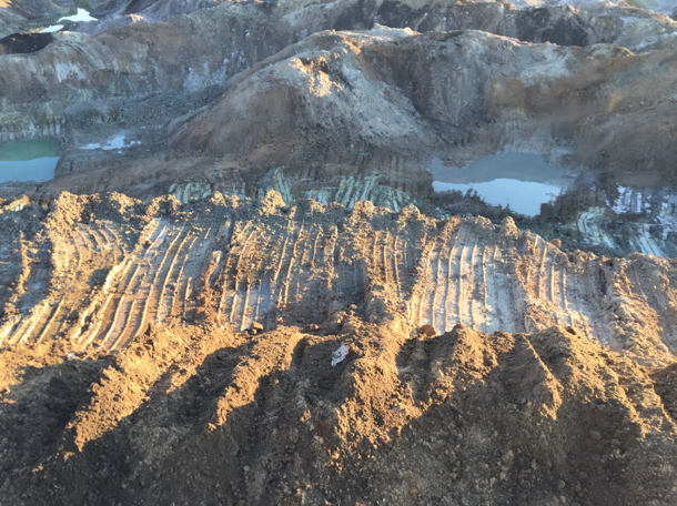
In this video clip, you probably saw the greenish colored material at the bottom. That is the phosphate matrix, and in this next picture, you can see it as well.
Evaluating the Phosphate Matrix
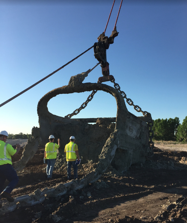
You’ll recall from our discussion of mine planning, that mineral processing plants are designed to perform best when the feed into the plant has characteristics that lie within a fairly narrow range. When the mined material is outside of this range, the practice is to blend loads of material from different mining faces to achieve the desired feed to the plant. This is true in phosphate mining as well. How do you know the qualities of the ore being mined at a given location on a given day? You send in the geologists to take samples and visually inspect the ore. In this next picture, you can see the geologist, accompanied by operations personnel, preparing to sample the phosphate matrix in the drag bucket.
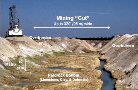
Now that we have a clearer understanding of this phase of the operation, let’s look at the dimensions of a typical strip or cut.
