8.5.7: A Closer Look
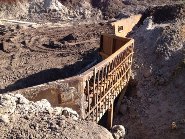
Let’s look at this construction in more detail. Looking at the next picture, we have a hole that has been dug, and they call it a “pit.” The pit is bisected by the steel grate, which they refer to as the “pit trap.” To the left of the grate, we have the hydraulic monitor, and this is where the dragline deposits the phosphate matrix. On the right side of the grate, we have the slurry intake pipe. In this photo, the intake has been lifted above the water line. Normally, the intake is submerged below the water line.
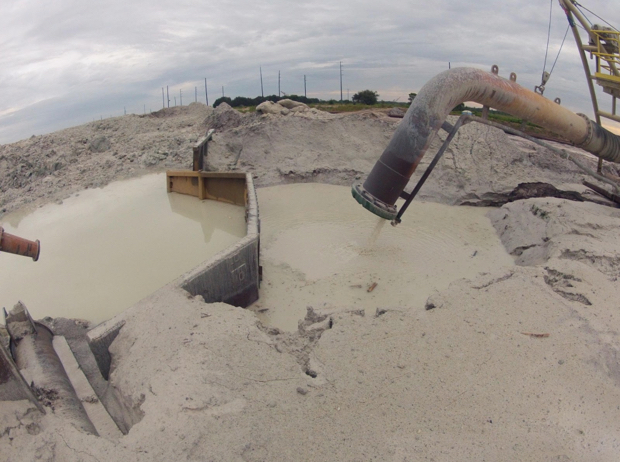
In this next photo, we can see more clearly the construction of the pit and pit trap.
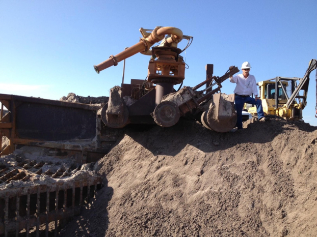
The next step in the construction of the pit is to install the monitor. Small dozers are used to construct the pit and to do the grading around it. In this next photo, look to the right of the worker. Do you see the specially outfitted tractor with the winch/crane assembly? This is what they use to move and position the monitors, pit traps, pumps, and related assemblies.
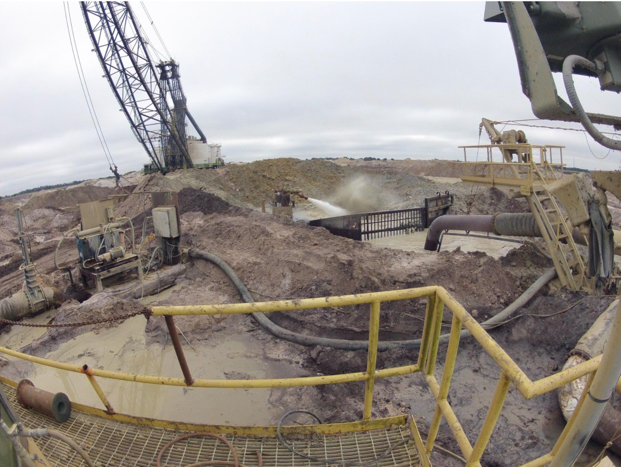
The next picture provides a wide-angle view of the pit and related equipment.